Nitrogen production system for producing nitrogen with different purities and nitrogen production process thereof

a nitrogen production system and nitrogen production technology, applied in lighting and heating apparatus, solidification, refrigeration and liquid storage, etc., can solve the problems of increasing electric power consumption, difficult to remove argon by chemical process such as adsorption process, and reducing recovery percentage, so as to achieve the effect of contributing to electric power saving

Active Publication Date: 2021-10-19
LAIR LIQUIDE SA POUR LETUDE & LEXPLOITATION DES PROCEDES GEORGES CLAUDE
View PDF12 Cites 0 Cited by
  • Summary
  • Abstract
  • Description
  • Claims
  • Application Information

AI Technical Summary

Benefits of technology

[0007]In the light of the aforementioned circumstances, an object of the present invention is to provide a nitrogen production system that can produce high purity nitrogen containing a desired concentration of oxygen and ultrahigh purity nitrogen containing a desired concentration of argon in a single rectifying column while removing the above described disadvantage and suppressing increase in electric power consumption, and a production process thereof. Further, the present invention provides a nitrogen production system that can precisely control a production amount of ultrahigh purity nitrogen and an argon concentration thereof by continuously measuring oxygen in high purity nitrogen, and a nitrogen production process thereof.
[0047]According to the above described configuration, waste gas containing a lot of low-boiling point impurities is separated in the condenser upper part, and the waste gas is introduced into the heat exchanger as the heat medium through the waste gas introduction pipe and the expansion turbine, exchanges heat with the material air, and thereafter is discharged. The waste gas is introduced into the expansion turbine, has the temperature reduced by expanding in the expansion turbine, and is introduced into the heat exchanger. The waste gas the temperature of which is reduced exchanges heat with the material air in the heat exchanger, and the cooled material air is introduced into the rectifying unit, so that the expansion turbine plays a role of keeping cold heat balance of nitrogen separation.

Problems solved by technology

However, since argon is chemically inert, it is difficult to remove argon by a chemical process such as an adsorption process.
Reduction in recovery percentage has a problem of involving increase in electric power consumption accompanying increase in a necessary material air amount.
However, in general, the height of the nitrogen rectifying column is very high (for example, 50 m), and increasing the theoretical plate number results in extension of the rectifying column, which is not realistic industrially.
However, continuous measurement of the concentration of argon in nitrogen is difficult in general.
The Ar content is very small in ultrahigh purity nitrogen, and measurement is especially difficult irrespective of whether continuous measurement or discontinuous measurement is used.

Method used


Image

  • Nitrogen production system for producing nitrogen with different purities and nitrogen production process thereof
  • Nitrogen production system for producing nitrogen with different purities and nitrogen production process thereof
  • Nitrogen production system for producing nitrogen with different purities and nitrogen production process thereof

Examples


embodiment 1

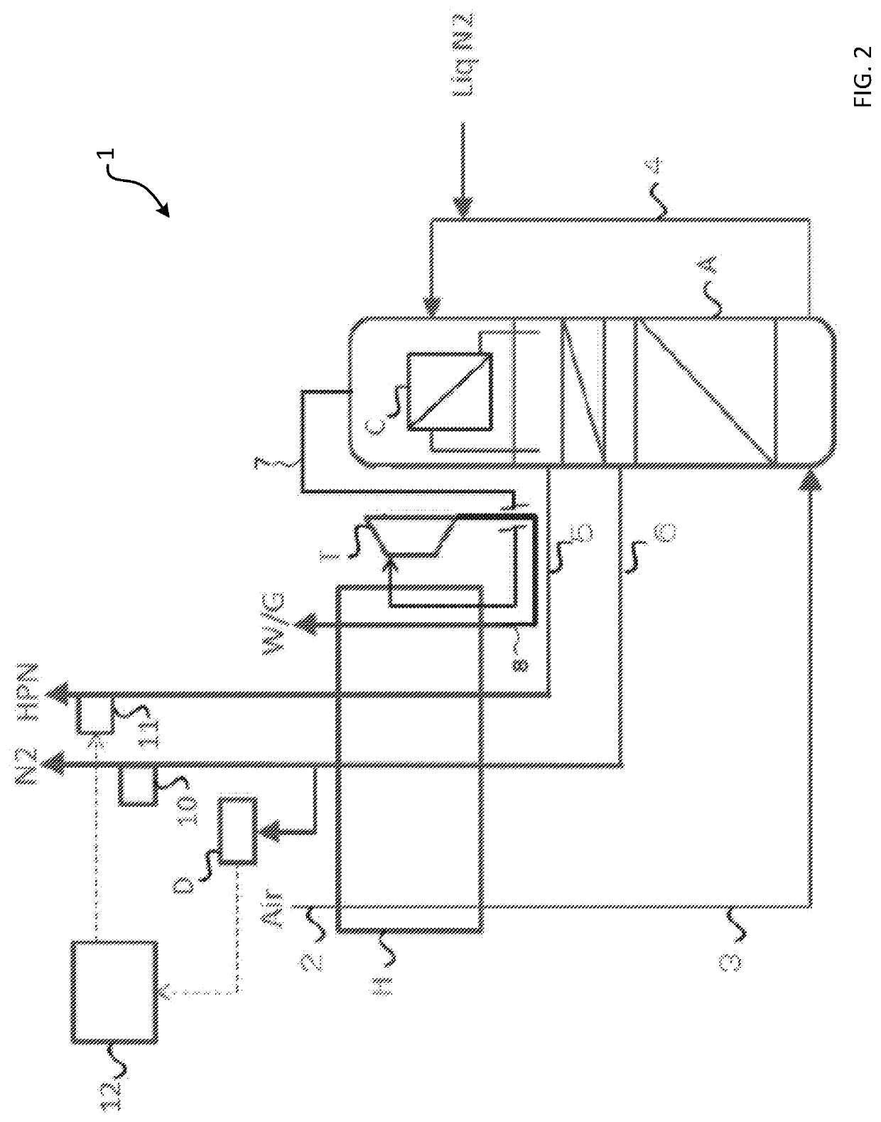
[0070]A nitrogen production system 1 of embodiment 1 will be described with use of FIG. 2. The nitrogen production system 1 has a heat exchanger H, a nitrogen rectifying column including a rectifying unit A and a condenser C located in a column top, a material air intake pipe 2 for feeding material air to cool the material air in the heat exchanger H, a material air introduction pipe 3 for feeding the cooled material air to the rectifying unit A, an oxygen-enriched liquefied gas introduction pipe 4 that derives an oxygen-enriched liquefied gas from the lower part of the rectifying unit A and introduces the oxygen-enriched liquefied gas into the condenser C to cool an inside of the condenser C, an ultrahigh purity nitrogen extraction pipe 5 that derives ultrahigh purity nitrogen from an upper plate of the rectifying unit A and introduces the ultrahigh purity nitrogen into the heat exchanger H, and a high purity nitrogen extraction pipe 6 that derives high purity nitrogen from an inte...

example

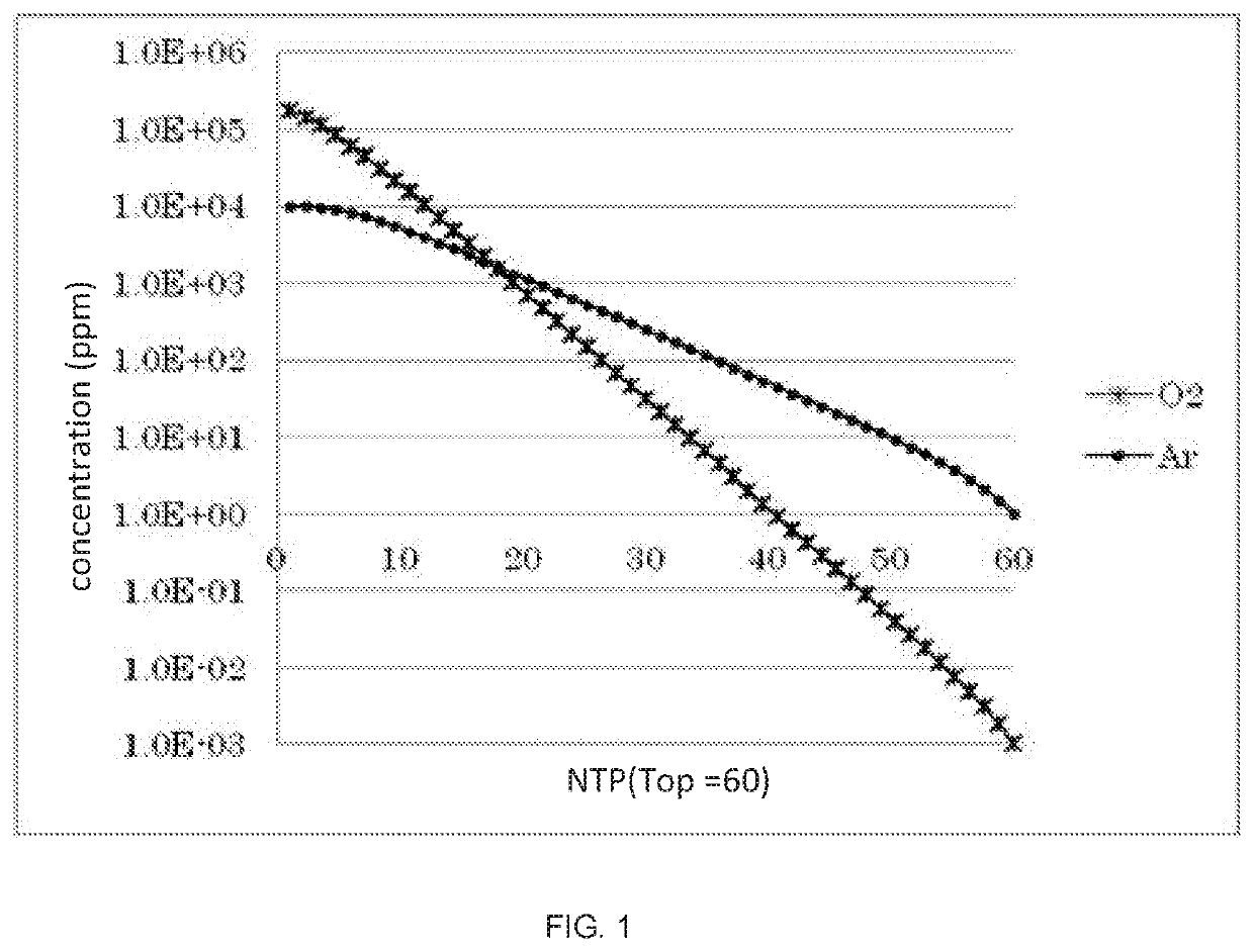
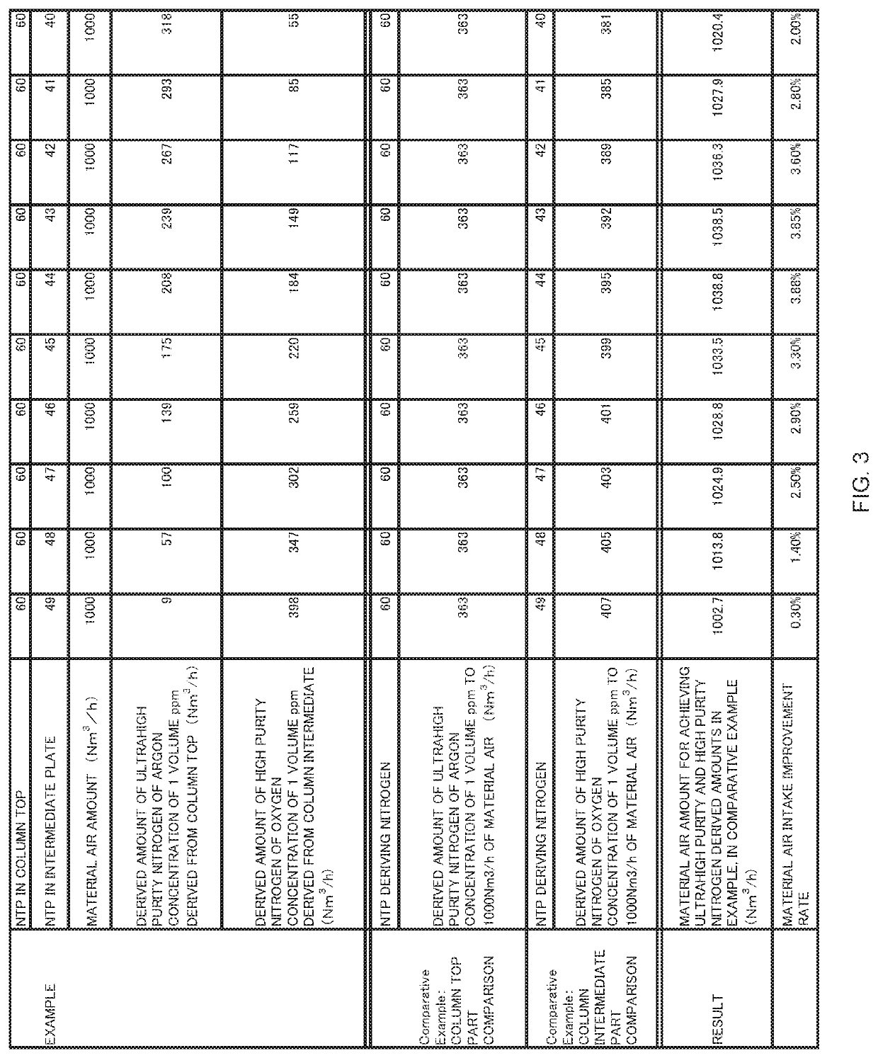
[0084]The inventors calculate the derived amounts of high purity nitrogen (the oxygen concentration is 1 volume ppm) and ultrahigh purity nitrogen (the Ar concentration is 1 volume ppm) according to the change in the position of the intermediate plate, in the conditions of the rectifying unit of the number of theoretical plates of 60 and the material air amount of 1000 Nm3 / h by simulation, and a result thereof is illustrated in FIG. 3. Further, FIG. 3 also illustrates an improvement efficiency in the case of being compared with the conventional art of extracting the same amount ultrahigh purity nitrogen (the Ar concentration is 1 volume ppm) from the rectifying column of the number of theoretical plates of 60, and extracting the same amounts of high purity nitrogen (the oxygen concentration is 1 volume ppm) from different rectifying columns of the numbers of theoretical plates of 49 to 40.

[0085]In the present simulation, an intermediate plate is within a range from a position of the...

embodiment 2

[0098]A process of producing nitrogen with different purities of embodiment 2 will be described. The process of embodiment 2 can be favorably executed by using the system of the above described embodiment 1.

[0099]A nitrogen production process of processing nitrogen by low temperature distillation includes

[0100]a compression step of compressing material air;

[0101]a removal step of removing predetermined impurities from the material air compressed in the compression step,

[0102]a cooling step of cooling the material air from which the impurities are removed in the removal step by a heat exchanger,

[0103]a first introduction step of introducing the material air cooled by the heat exchanger into a lower part from the rectifying unit position of a nitrogen rectifying column including a rectifying unit and a condenser located in a column top,

[0104]a second introduction step of introducing an oxygen-enriched liquefied gas into the condenser from the lower part from the rectifying unit positi...


PUM


Abstract

A nitrogen production system that can produce high purity nitrogen containing a desired concentration of oxygen and ultrahigh purity nitrogen containing a desired concentration of argon in a single rectifying column while restraining increase in electric power consumption and a production process thereof are provided. The method can include the steps of rectifying a cooled and compressed air stream in the rectifying column; withdrawing the ultrahigh purity nitrogen stream from a top portion of the nitrogen rectifying column, warming the ultrahigh purity nitrogen stream in a heat exchanger, and then recovering the ultrahigh purity nitrogen stream from the heat exchanger; and withdrawing a high purity nitrogen stream from a rectification section of the nitrogen rectifying column, warming the high purity nitrogen stream in the heat exchanger, and then recovering the high purity nitrogen stream from the heat exchanger.

Description

CROSS REFERENCE TO RELATED APPLICATIONS[0001]This application claims the benefit of priority under 35 U.S.C. § 119 (a) and (b) to Japanese patent application No. JP2017-83203, filed Apr. 19, 2017, the entire contents of which are incorporated herein by reference.BACKGROUND OF THE INVENTIONField of the Invention[0002]The present invention relates to a nitrogen production apparatus for producing nitrogen with different purities and a production process thereof, and particularly to an apparatus and a process for producing ultrahigh purity nitrogen gas with a low argon (hereinafter, also referred to as Ar) content and nitrogen gas having a predetermined concentration of oxygen content in a single rectifying column.Description of the Related Art[0003]Conventionally, material air that is cooled in a heat exchanger has been introduced into a lower part of a nitrogen rectifying column, and has been rectified, from which nitrogen has been separated to a column top, and liquid air having a hi...

Claims


Application Information

Patent Timeline
Patent Type & Authority Patents(United States)
IPC IPC(8): F25J3/04
CPCF25J3/04309F25J3/044F25J3/04018F25J3/0426F25J3/04187F25J3/04284F25J3/04296F25J3/04769F25J2210/42F25J2215/42F25J2215/44F25J2220/50F25J2230/40F25J3/04109F25J3/04345F25J3/04775F25J3/048F25J2200/72
Inventor HIROSE, KENJIUTSUNOMIYA, HIROFUMINAGATA, DAISUKENISHI, YASUHARUTOMITA, SHINJI
Owner LAIR LIQUIDE SA POUR LETUDE & LEXPLOITATION DES PROCEDES GEORGES CLAUDE
Why Eureka
Try Eureka