
Illumination device and method for avoiding an over-power or over-current condition in a power converter

a technology of over-current and power converter, which is applied in the direction of lighting apparatus, electrical equipment, light sources, etc., can solve the problems of power converter overheating and failure, and the safe maximum power/current level attributed to the power converter is not always consistent, so as to increase the drive current

Active Publication Date: 2016-11-01
LUTRON TECH CO LLC
View PDF284 Cites 37 Cited by
  • Summary
  • Abstract
  • Description
  • Claims
  • Application Information

AI Technical Summary

Benefits of technology

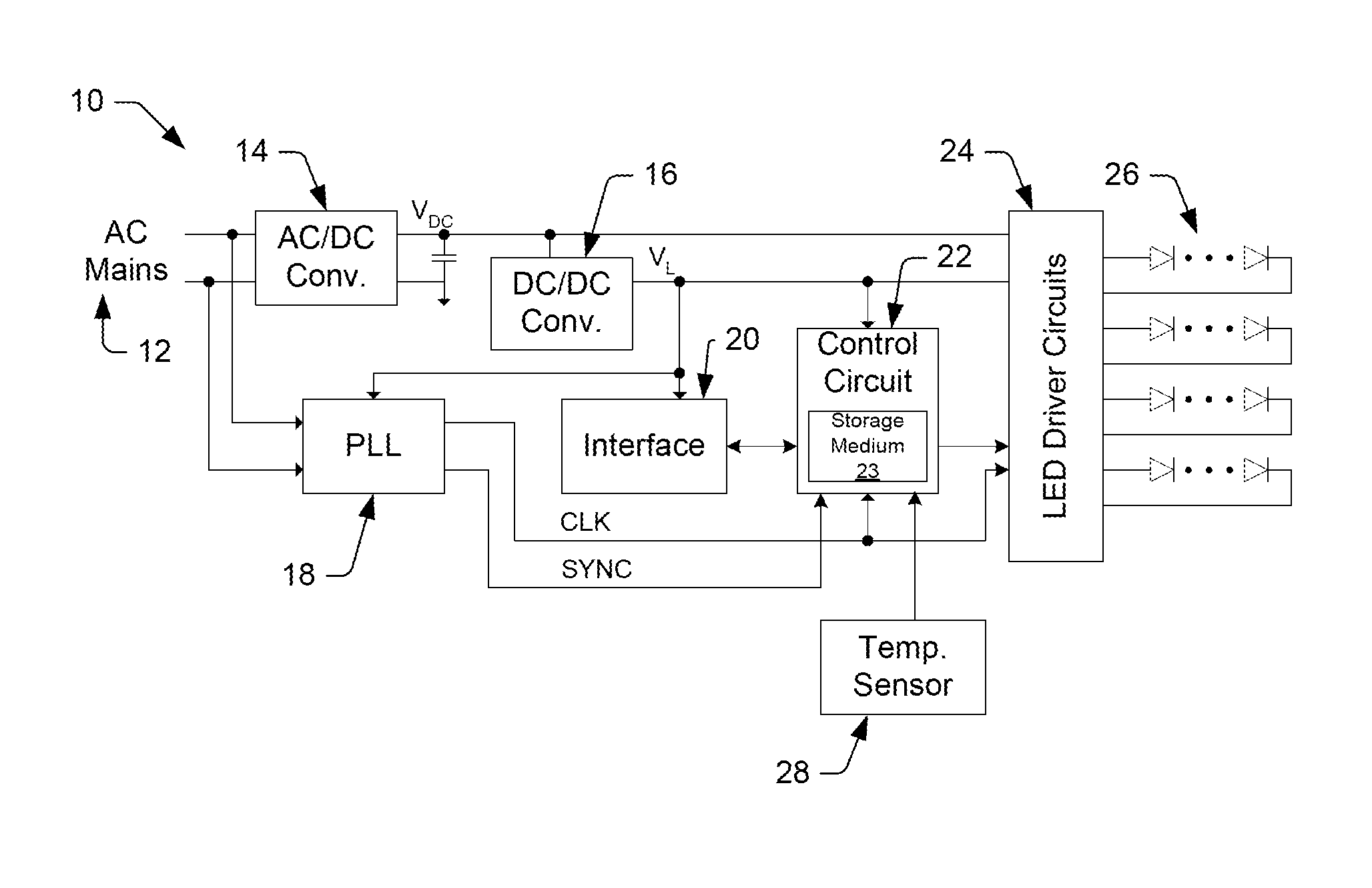
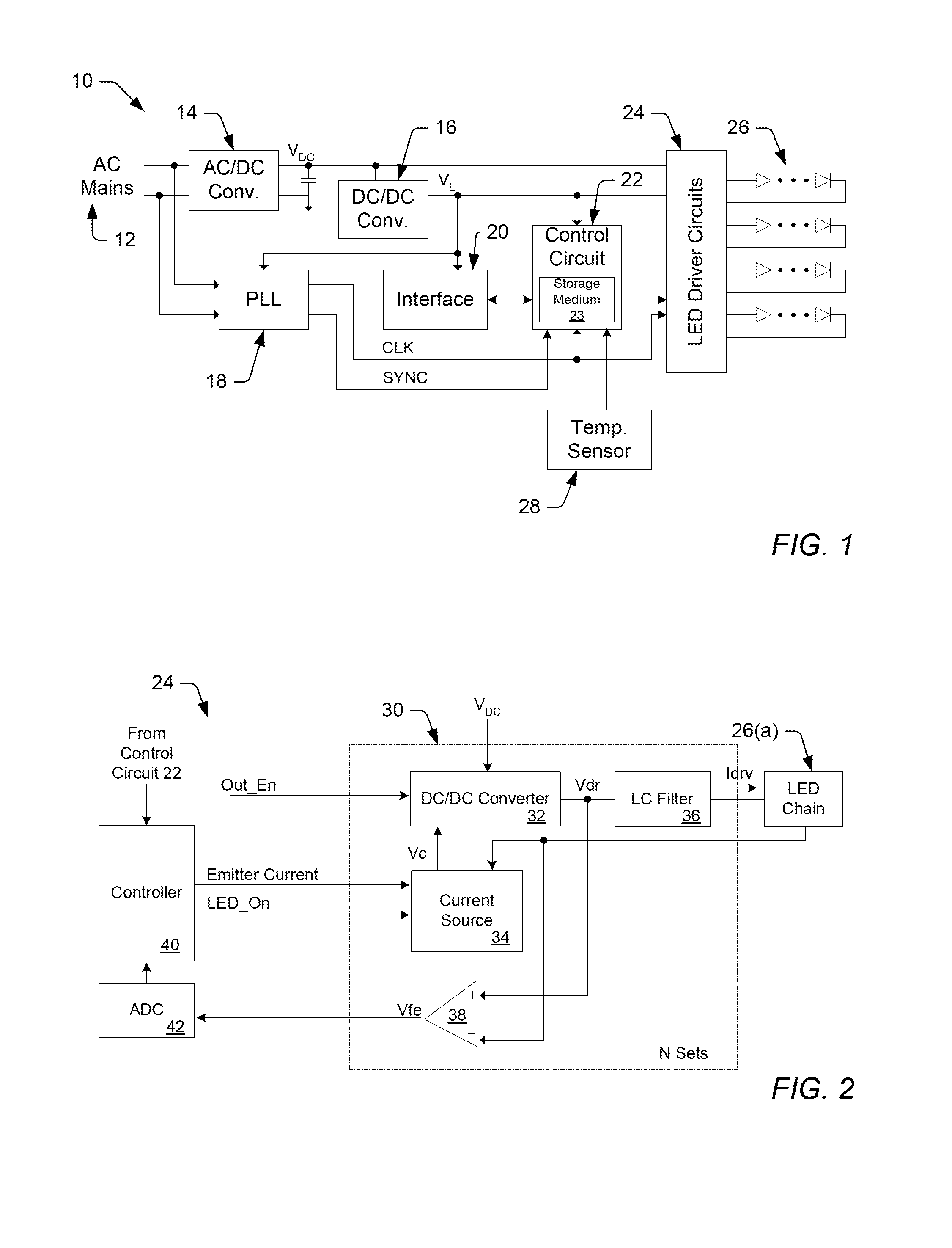
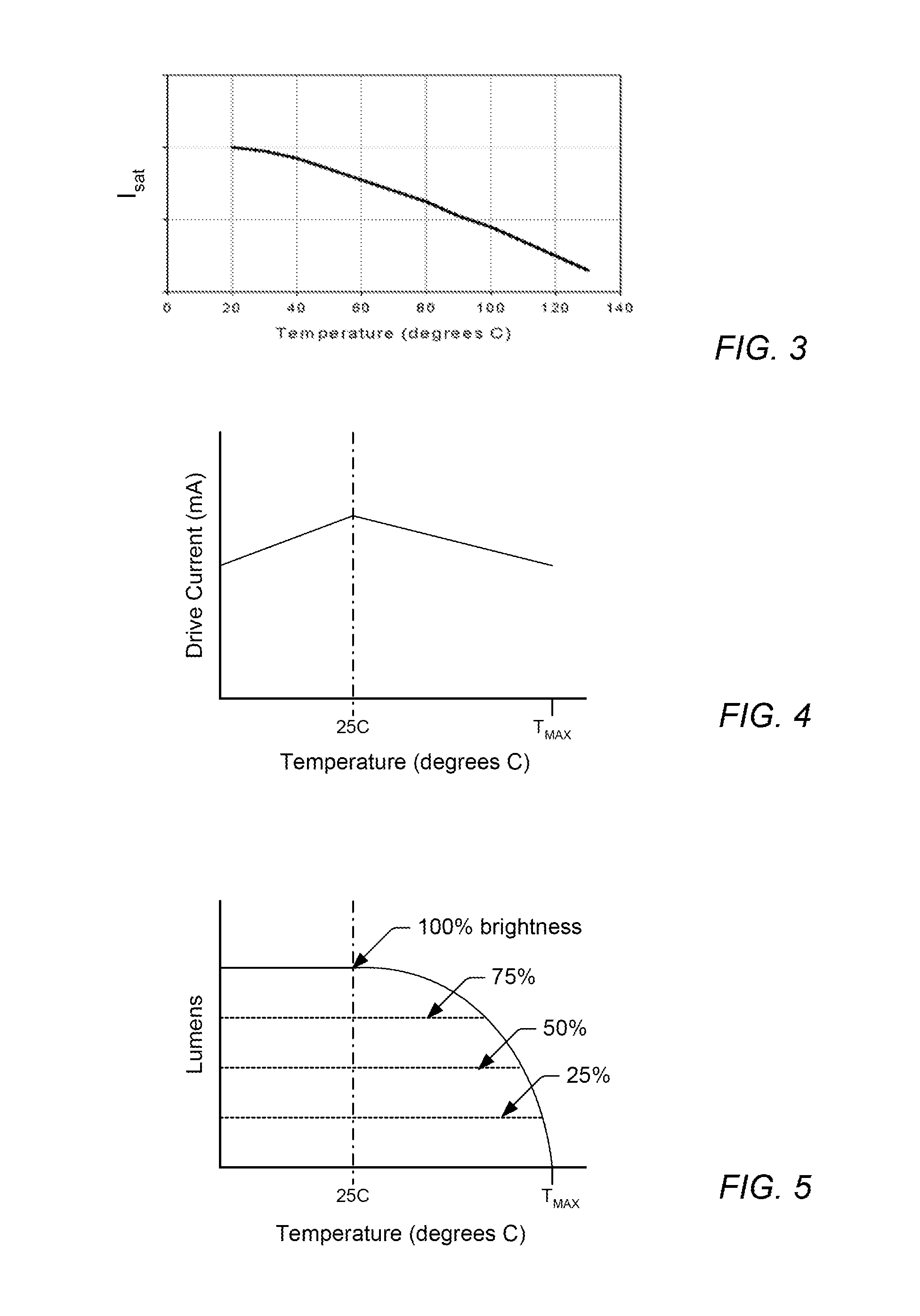
This patent describes a control circuit and method for LED lights that ensures safe and efficient operation. The control circuit determines a maximum safe temperature and adjusts the brightness and chromaticity settings to achieve the desired appearance. It also monitors the operating temperature and adjusts the scale factor to prevent over-power or over-current conditions. This ensures a precise and efficient output from the LED lights, even at high temperatures.

Problems solved by technology

As described in more detail herein, the first power converter may have a maximum safe power level and the second power converters may each have a maximum safe current level, above which the inductive core of the power converters saturates, potentially causing the power converter to overheat and fail.
The maximum safe power / current levels attributed to the power converters are not always consistent and tend to vary with operating temperature, once the operating temperature exceeds a predetermined safe temperature.

Method used


Image

  • Illumination device and method for avoiding an over-power or over-current condition in a power converter
  • Illumination device and method for avoiding an over-power or over-current condition in a power converter
  • Illumination device and method for avoiding an over-power or over-current condition in a power converter

Examples


Embodiment Construction

[0052]An LED generally comprises a chip of semiconducting material doped with impurities to create a p-n junction. As in other diodes, current flows easily from the p-side, or anode, to the n-side, or cathode, but not in the reverse direction. Charge-carriers—electrons and holes—flow into the junction from electrodes with different voltages. When an electron meets a hole, it falls into a lower energy level, and releases energy in the form of a photon (i.e., light). The wavelength of the light emitted by the LED, and thus its color, depends on the band gap energy of the materials forming the p-n junction of the LED.

[0053]Red and yellow LEDs are commonly composed of materials (e.g., AlInGaP) having a relatively low band gap energy, and thus produce longer wavelengths of light. For example, most red and yellow LEDs have a peak wavelength in the range of approximately 610-650 nm and approximately 580-600 nm, respectively. On the other hand, green and blue LEDs are commonly composed of m...


PUM


Abstract

An illumination device and methods are provided herein for avoiding over-current and over-power conditions in one or more power converters included within the illumination device. The illumination device may include at least a plurality of light emitting diode (LED) chains, a driver circuit, at least one power converter, and a control circuit. In some embodiments, the control circuit may be generally configured for determining a maximum safe current level and / or a maximum safe power level attributed to the power converter(s) at a present operating temperature, and for adjusting respective drive currents supplied to the plurality of LED chains by the driver circuit, so as not to exceed the maximum safe current level or the maximum safe power level at the present operating temperature. In some embodiments, a temperature sensor may be included within the illumination device for measuring the operating temperature presently associated with the power converter(s).

Description

RELATED APPLICATIONS[0001]This application is related to commonly assigned U.S. patent application Ser. Nos. 14 / 314,451, which published on Dec. 31, 2015 as U.S. Patent Application Publication No. 2015 / 0377699; 14 / 314,530, which published on Dec. 31, 2015 as U.S. Patent Application Publication No. 2015 / 0382422; 14 / 314,580, which issued on Jul. 12, 2016 as U.S. Pat. No. 9,392,663; 14 / 471,057, which issued on Jul. 12, 2016 as U.S. Pat. No. 9,392,660; and 14 / 471,081, which published on Mar. 3, 2016 U.S. Patent Application Publication No. 2016 / 0066384. The entirety of these applications is incorporated herein by reference.BACKGROUND OF THE INVENTION[0002]1. Field of the Invention[0003]This invention relates to illumination devices comprising light emitting diodes (LEDs) and, more particularly, to illumination devices and methods for avoiding an over-power or over-current condition. Specifically, illumination devices and methods are provided herein for adjusting the drive currents suppli...

Claims


Application Information

Patent Timeline
IPC IPC(8): H05B33/08H05B44/00
CPCH05B33/0809H05B33/0824H05B33/0854H05B33/0872H05B45/28H05B45/12H05B45/3725H05B45/375H05B45/18H05B45/44H05B45/56
Inventor LEWIS, JASONBOCOCK, RYAN MATTHEWSAVAGE, JOSEPHLUU, JIVAN JAMESKNAPP, DAVID
Owner LUTRON TECH CO LLC
Learn More