Exposure method, exposure apparatus, and device manufacturing method

a technology of exposure apparatus and manufacturing method, which is applied in the direction of microlithography exposure apparatus, printers, instruments, etc., can solve the problems of exposure aberration, non-negligible measurement errors, and magnification errors of projection optical systems, etc., and achieve the effect of high accuracy and short tim

Inactive Publication Date: 2016-12-06
CANON KK
View PDF12 Cites 5 Cited by
  • Summary
  • Abstract
  • Description
  • Claims
  • Application Information

AI Technical Summary

Benefits of technology

[0007]The present invention provides an exposure method that is advantageous for predicting the fluctuation in the imaging characteristics for each exposure condition in a short time with high accuracy.

Problems solved by technology

An important factor that influences the alignment accuracy includes a magnification error of the projection optical system.
Here, it is known that, when the projection optical system absorbs a part of the exposure energy, a heat generated by the absorption changes the temperature of the projection optical system, resulting in change in the optical characteristics such as the refractive index of the projection optical system, that is, resulting in occurrence of so-called thermal aberration (exposure aberration).
Consequently, non-negligible measurement errors may undesirably occur during alignment measurement.
Consequently, it becomes difficult to determine the aberration fluctuation coefficient under the second exposure condition with high accuracy.

Method used


Image

  • Exposure method, exposure apparatus, and device manufacturing method
  • Exposure method, exposure apparatus, and device manufacturing method
  • Exposure method, exposure apparatus, and device manufacturing method

Examples


Embodiment Construction

[0015]Hereinafter, preferred embodiments of the present invention will now be described with reference to the accompanying drawings.

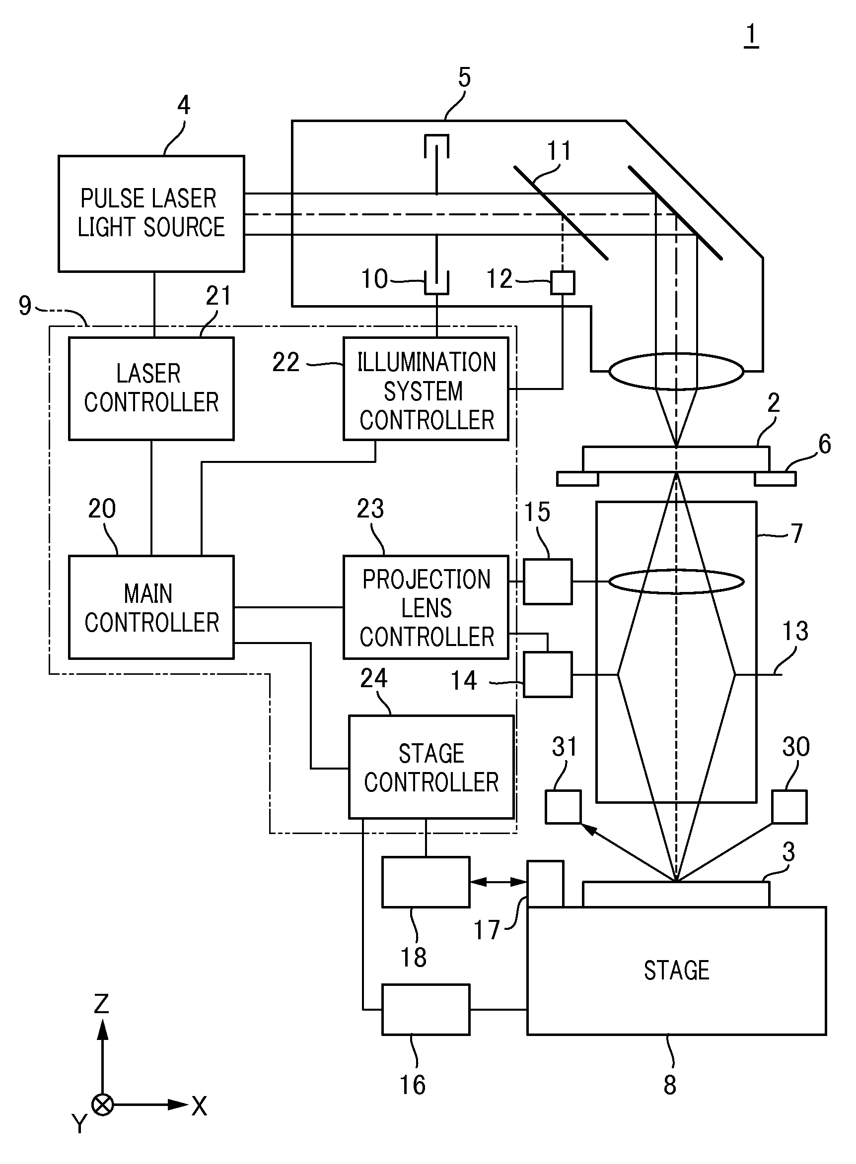
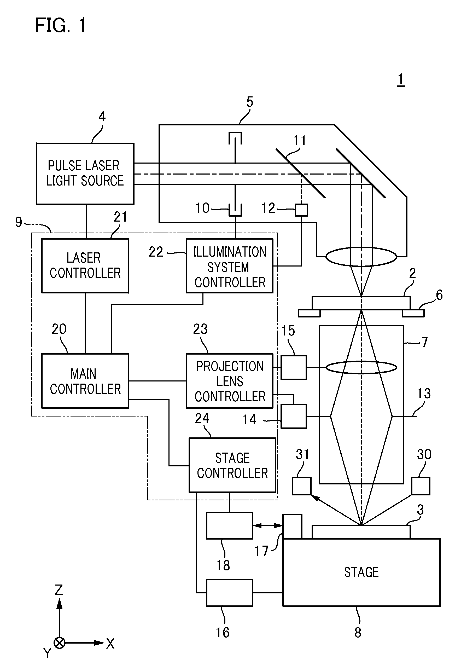
[0016]Firstly, a description will be given of the configuration of an exposure apparatus according to one embodiment of the present invention. FIG. 1 is a schematic view illustrating the configuration of an exposure apparatus 1 of the present embodiment. As an example, the exposure apparatus 1 is a projection type exposure apparatus that is used for the manufacturing process of a semiconductor device and exposes a pattern (e.g., circuit pattern) formed on a reticle (original) 2 to a wafer 3 (substrate) in a step-and-repeat system. Firstly, the exposure apparatus 1 includes a pulse laser light source 4, an illumination system 5, a reticle stage 6, a projection optical system 7, a stage 8, and a controller 9.

[0017]The pulse laser light source 4 in which a gas such as KrF, ArF, or the like is sealed emits light (laser) having a wavelength in a far ultravio...


PUM

PropertyMeasurementUnit
wavelengthaaaaaaaaaa
imaging characteristicaaaaaaaaaa
photosensitiveaaaaaaaaaa

Abstract

Provided is an exposure method that includes setting a first exposure condition so as to calculate a coefficient for predicting the fluctuation in the imaging characteristics of the projection optical system under a certain exposure condition; determining the coefficient and a permissible value calculated from aberration measurement reproducibility based on a fluctuation characteristic model; calculating a predicted amount of the fluctuation in the imaging characteristics under the first exposure condition based on the coefficient; determining whether or not the predicted amount is less than the permissible value for each time instant; and starting calculation of the predicted amount of the fluctuation in the imaging characteristics under a second exposure condition at the time at which it is determined by the determining that the predicted amount is less than the permissible value.

Description

BACKGROUND OF THE INVENTION[0001]1. Field of the Invention[0002]The present invention relates to an exposure method and an exposure apparatus, and a device manufacturing method.[0003]2. Description of the Related Art[0004]An exposure apparatus is an apparatus that transfers a pattern of an original (reticle or the like) onto a photosensitive substrate (e.g., wafer or the like where the surface thereof is coated with a resist layer) via a projection optical system in a lithography step included in manufacturing steps for a semiconductor device, a liquid crystal display device, and the like. One of the important optical characteristics of such an exposure apparatus is alignment accuracy with which the patterns in a plurality of steps are overlaid accurately. An important factor that influences the alignment accuracy includes a magnification error of the projection optical system. The required pattern size shrinks every year, and accordingly a requirement for an improvement in alignmen...

Claims


Application Information

Patent Timeline
Patent Type & Authority Patents(United States)
IPC IPC(8): G03B27/68G03F7/20
CPCG03F7/705G03F7/706G03F7/70883
Inventor OZAWA, KAZUYOSHI
Owner CANON KK
Why Eureka
Try Eureka