
Hydroisomerization catalyst, process for producing the same, method of dewaxing hydrocarbon oil, and process for producing lube base oil

a technology of hydroisomerization catalyst and hydroisomerization process, which is applied in the direction of catalyst activation/preparation, hydrocarbon oil treatment products, physical/chemical process catalysts, etc., can solve the problems of difficult to obtain and the inability to obtain target isoparaffin fractions with an economical yield, and achieves low cracking activity , high isomerization selectivity, the effect of high yield

Active Publication Date: 2016-12-13
JX NIPPON OIL & ENERGY CORP
View PDF33 Cites 0 Cited by
  • Summary
  • Abstract
  • Description
  • Claims
  • Application Information

AI Technical Summary

Benefits of technology

The present invention introduces a new type of catalyst for hydroisomerization, which is effective in converting normal paraffins in hydrocarbon oils into isoparaffins while minimizing cracking activity. The new catalyst has a high isomerization selectivity, allowing for the production of high-quality lubricating oils and fuel base oils from normal paraffin-containing oils. The invention also provides methods for dewaxing hydrocarbon oils using this new catalyst and manufacturing high-performance lube-oil base oils from normal paraffin-containing oils.

Problems solved by technology

Even by the manufacturing method described above in Patent Document 1, since the isomerization selectivity of a catalyst cannot be said to be sufficient and the cracking activity is not sufficiently suppressed, it is difficult to obtain, with a high yield, isoparaffin fractions suitable for desired lube-oil base oils and fuel base oils from hydrocarbon oils containing normal paraffin components.
In this case, the cracking of normal paraffins and / or isoparaffins being isomerized products become active, and target isoparaffin fractions cannot be obtained with an economical yield.

Method used


Image

  • Hydroisomerization catalyst, process for producing the same, method of dewaxing hydrocarbon oil, and process for producing lube base oil
  • Hydroisomerization catalyst, process for producing the same, method of dewaxing hydrocarbon oil, and process for producing lube base oil

Examples


example 2

2. Manufacture of a Lube-Oil Base Oil by Dewaxing a Wax

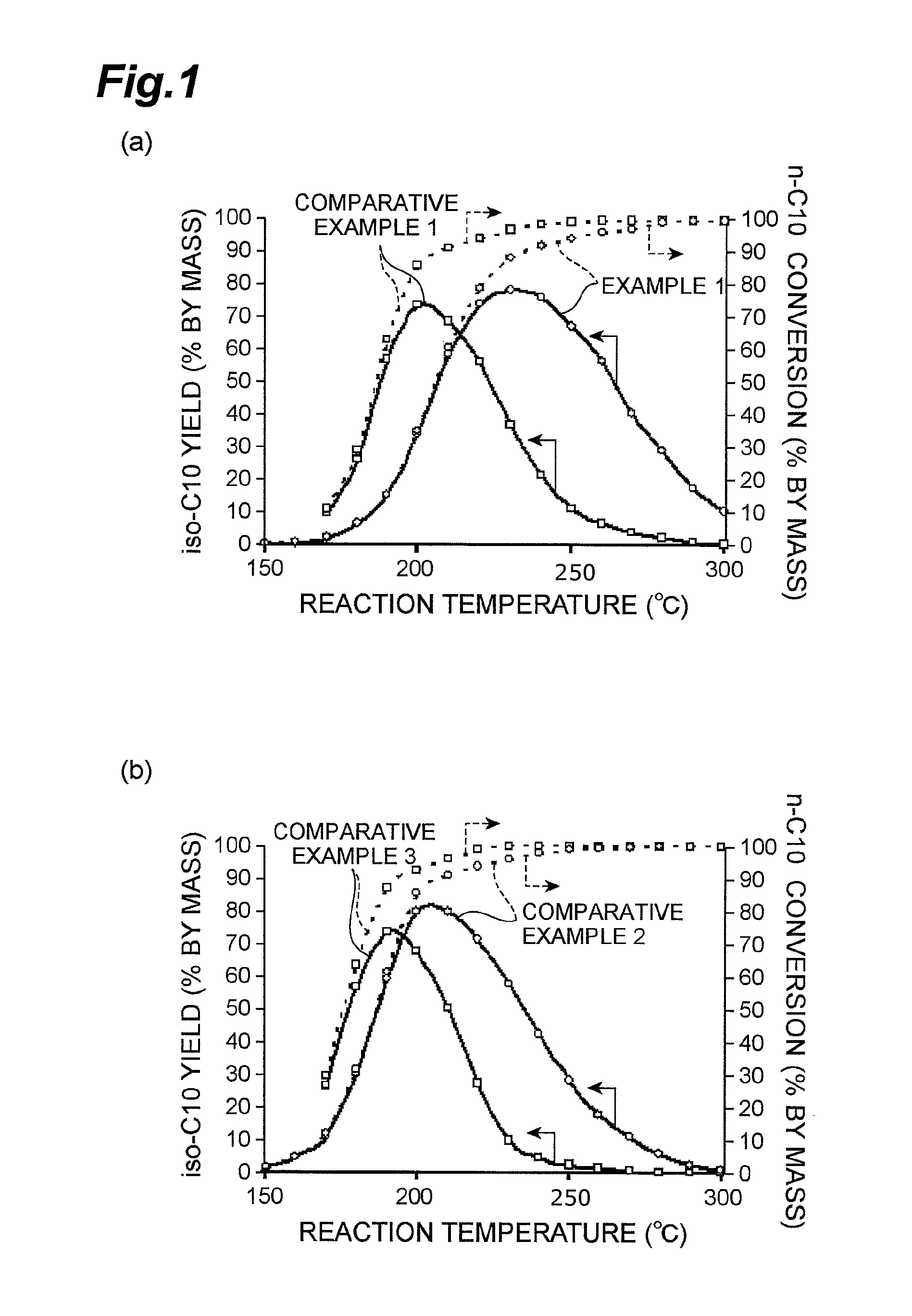
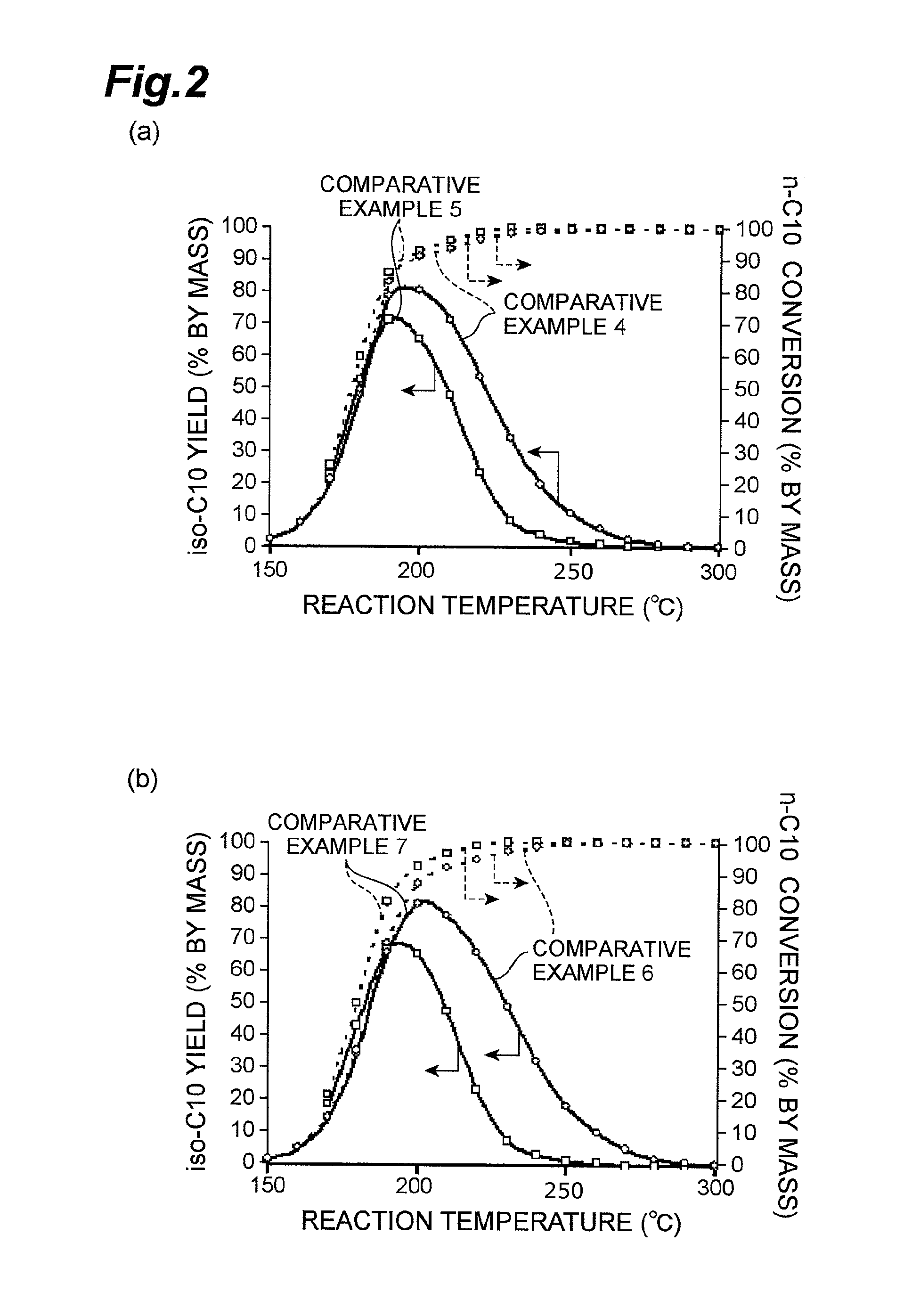
[0136]A hydroisomerization catalyst was manufactured by using the ZSM-22[27]IE obtained as described above as a constituent and molding it together with a binder; and a wax originated from a petroleum was dewaxed by the hydroisomerization using the catalyst to manufacture a lube-oil base oil.

2-1. Manufacture of a Catalyst

2-1-1. Manufacture of ZSM-22[27]IE

[0137]ZSM-22[27]IE was prepared as in Example 1.

2-1-2. Binder Formulation, Molding, and Calcination

[0138]ZSM-22[27]IE and alumina as a binder were formulated in a mass ratio of ZSM-22[27]IE:alumina of 70:30; and a small amount of ion-exchange water was added thereto, and the mixture was kneaded, and molded by extrusion molding to obtain a cylindrical molded product of about 1.5 mm in diameter and about 5 mm in length. Then, the molded product was calcined in an air flow at 400° C. for 3 hours.

2-1-3. Platinum Carrying, and Calcination

[0139]The calcined molded product obtained as ...


PUM

PropertyMeasurementUnit
sizeaaaaaaaaaa
temperatureaaaaaaaaaa

Abstract

A hydroisomerization catalyst of the present invention is obtained by calcining a catalyst composition containing an ion-exchanged molecular sieve or a calcined product thereof, and at least one metal selected from the group consisting of metals of Groups 8 to 10 in Periodic Table of the elements, molybdenum and tungsten, carried on the ion-exchanged molecular sieve or the calcined product thereof, wherein the ion-exchanged molecular sieve is obtained by ion-exchanging a molecular sieve, which includes nanocrystals having a pore structure of ten-membered rings or eight-membered rings and having a ratio of the pore volume to the external surface area ([pore volume] / [external surface area]) of 2.0×10⁻⁴ mL / m2 to 8.0×10⁻⁴ mL / m2 and contains an organic template, in a solution containing a cationic species.

Description

TECHNICAL FIELD[0001]The present invention relates to a novel hydroisomerization catalyst and a method for manufacturing the catalyst, and a method for dewaxing a hydrocarbon oil and a method for manufacturing a lube-oil base oil using the hydroisomerization catalyst.BACKGROUND ART[0002]Among petroleum products, for example, lube-oils, gas oils and jet fuels are products whose cold flow property is given importance to. Therefore, base oils used in these products are desirably ones from which wax components such as normal paraffins and slightly branched isoparaffins causing reduction of cold flow property are completely or partially removed, or in which the wax components are converted to components other than the wax components. Hydrocarbons obtained by Fischer-Tropsch synthesis method are recently paid attention as feedstock oils when lube-oils and fuels are manufactured in view of containing no environmental load substances such as sulfur compounds, but the hydrocarbons also conta...

Claims


Application Information

Patent Timeline
Patent Type & Authority Patents(United States)
IPC IPC(8): B01J29/06C10G25/03B01J37/00B01J29/068C01B39/48C10G45/64B01J29/064B01J29/076B01J29/72B01J29/78B01J29/74B01J35/02B01J35/10B01J35/00
CPCC10G45/64B01J29/064B01J29/068B01J29/076B01J29/7284B01J29/7484B01J29/7884B01J35/026B01J37/0009C01B39/48B01J2229/40B01J2229/42C10G2300/1022C10G2300/1085C10G2400/10B01J29/7461B01J29/7492B01J29/7861B01J29/7892B01J35/023B01J35/1014B01J35/1019B01J35/1038B01J2229/186B01J2229/20B01J35/40B01J35/613B01J35/615B01J35/633B01J2235/30B01J35/55B01J2235/15B01J29/74B01J35/60C10G35/095B01J35/50
Inventor HAYASAKA, KAZUAKI
Owner JX NIPPON OIL & ENERGY CORP
Learn More