
Radioactive gas measurement apparatus and failed fuel inspection apparatus

a radiation measurement and fuel inspection technology, applied in the direction of material analysis by measuring secondary emission, x/gamma/cosmic radiation measurement, instruments, etc., can solve the problems of large and complicated measurement system, difficult to effectively eliminate annihilation, large and expensive radiation measurement apparatus, etc., and achieve the effect of simple configuration

Active Publication Date: 2016-12-13
HITACHI LTD
View PDF7 Cites 0 Cited by
  • Summary
  • Abstract
  • Description
  • Claims
  • Application Information

AI Technical Summary

Benefits of technology

The present invention is for a small and low-cost gas measurement apparatus and failed-fuel detection system that uses positron annihilation and gamma ray suppression. The invention is designed to have a simple configuration without requiring complicated radiation measurement systems. The technical effect of this invention is to provide a practical and affordable solution for detecting radioactive gas leaks in a simple and straightforward way.

Problems solved by technology

However, because the conventional radiation measurement apparatuses described in JP-A-7-218638 and JPA-2001-235546 include two radiation detection systems and two anticoincidence circuits therefor, there is a problem that the measurement system becomes large and complicated and thus the radiation measurement apparatuses become large and expensive if its shield system is included.
For this reason, the conventional radiation measurement apparatuses described in JP-A-2005-9890 and JP-A-2001-141829 have a problem that it is difficult to effectively eliminate annihilation gamma rays (511 keV) emitted from the positron emitter nuclide mixed in the fluid to be measured.

Method used


Image

  • Radioactive gas measurement apparatus and failed fuel inspection apparatus
  • Radioactive gas measurement apparatus and failed fuel inspection apparatus
  • Radioactive gas measurement apparatus and failed fuel inspection apparatus

Examples


Embodiment Construction

[0039]Embodiments of the present invention will be described hereinafter with reference to the accompanying drawings. Note that the same constituent element is given the same reference numeral to omit the duplicated description.

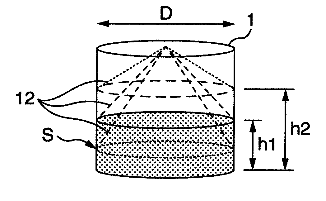
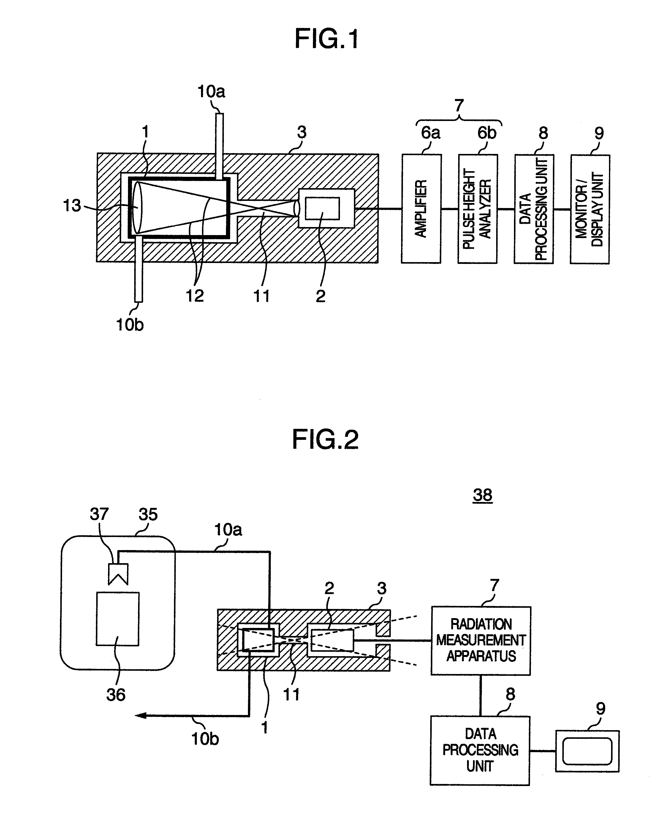
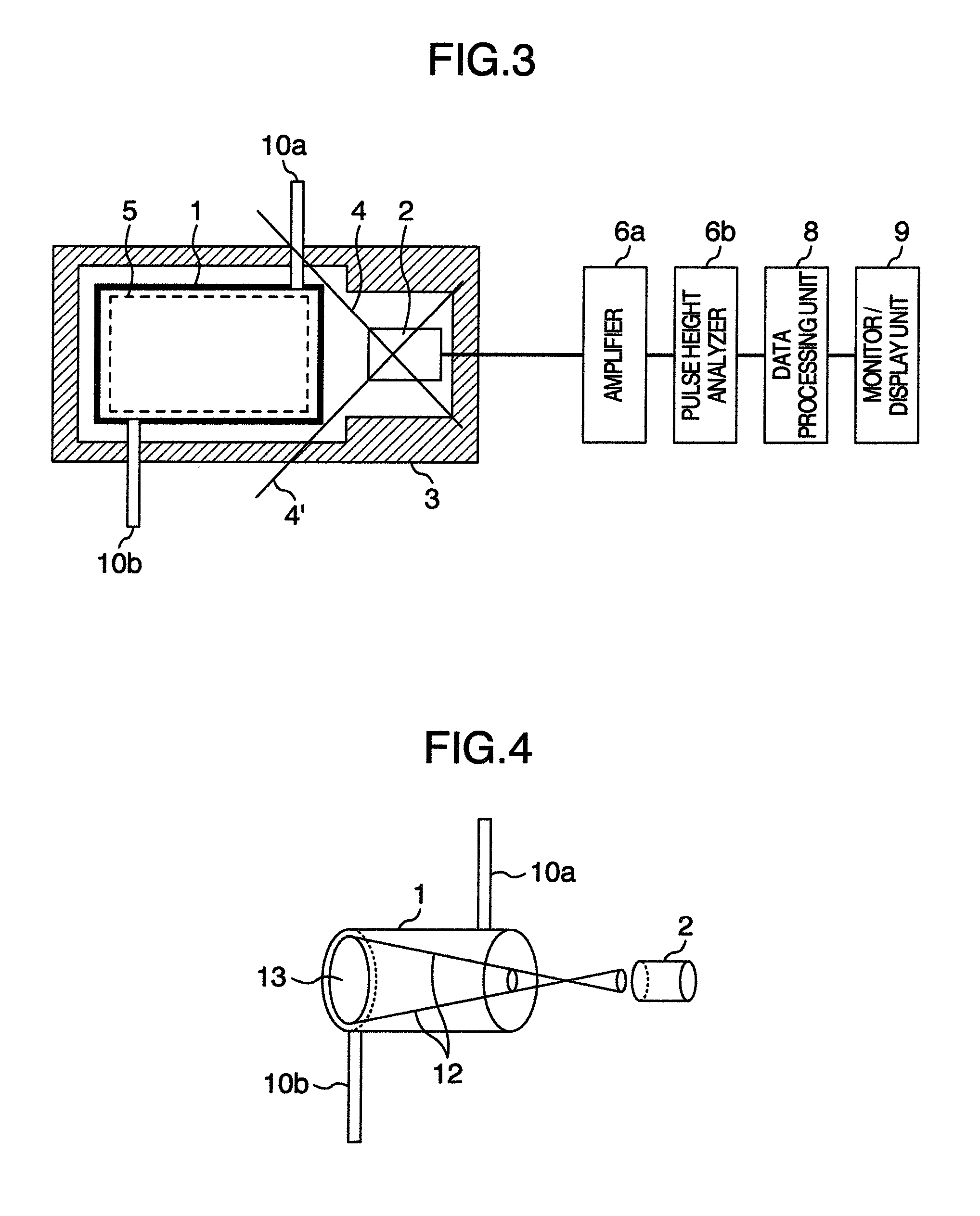
[0040]FIG. 1 is a view showing a positron annihilation gamma ray suppression type radioactive gas measurement apparatus of a first embodiment of the present invention. The positron annihilation gamma ray suppression type radioactive gas measurement apparatus of this embodiment comprises: a measurement cell 1 for introducing a measurement gas; a radiation detector 2 for measuring a radiation emitted from the measurement cell 1; a shield 3 having the measurement cell 1 and the radiation detector 2 provided therein and preventing incidence of a background radiation coming from an outside of the measurement cell 1; a measured-radioactive gas inlet pipe 10a for introducing a measured gas into the measurement cell 1 from an outside of the shield 3; a measured-radio...


PUM


Abstract

A radioactive gas measurement apparatus comprises: a radiation measurement cell comprising an inlet pipe and a discharge pipe, the radiation measurement cell introducing and discharging a radioactive gas containing a nuclide to be measured and a positron emitter nuclide through the inlet pipe and the discharge pipe; a radiation detector for measuring a radiation generated from the radioactive gas; and a radiation collimator allowing the radiation measurement cell to communicate with the radiation detector and setting a predetermined radiation measurement geometry condition between the radiation measurement cell and the radiation detector. Then, as the predetermined radiation measurement geometry condition, an inner wall area of the radiation measurement cell which the radiation detector views through the radiation collimator is set equal to or less than a half of a total inner wall area of the radiation measurement cell.

Description

BACKGROUND OF THE INVENTION[0001]Field of the Invention[0002]The present invention relates to radioactive gas measurement apparatuses. In particular, the present invention relates to a positron annihilation gamma ray suppression type radioactive gas measurement apparatus (hereinafter, also referred to as a “radioactive gas measurement apparatus”) and failed-fuel detection system which measure the radiation generated from a nuclide to be measured by significantly suppressing the influence of an annihilation gamma ray from a radioactive gas containing the nuclide to be measured and a positron emitter nuclide.[0003]Description of the Related Art[0004]Conventionally, in a nuclear power plant, the amount of a fission product contained in a primary coolant (nuclear reactor water) or a main steam is always monitored for the purpose of confirming the soundness of a nuclear reactor fuel. In particular, the nuclear reactor water or main steam often contains a lot of N-13 (nitrogen-13). For th...

Claims


Application Information

Patent Timeline
IPC IPC(8): G01T1/18G01T1/185G01T1/29H01J47/06H01J47/02
CPCG01T1/185G01T1/2935G01T1/18H01J47/02H01J47/06G01M3/20G01N33/0055G01N23/22G01N33/0027
Inventor KITAGUCHI, HIROSHITADOKORO, TAKAHIROUENO, KATSUNORIKUWABARA, HITOSHI
Owner HITACHI LTD
Learn More