
Catalysts

a catalyst and catalyst technology, applied in the field of catalysts, can solve the problems of reducing affecting the total process cost of the catalyst fabrication and the time required to prepare the catalyst, and the maximum amount of metal that can be deposited per impregnation step cannot be pre-defined, so as to increase the activity of the catalyst, improve the attrition resistance, and improve the effect of attrition resistan

Active Publication Date: 2016-12-27
SASOL TEKHNOLODZHI PROPRIEHJTEHRI LTD
View PDF11 Cites 1 Cited by
  • Summary
  • Abstract
  • Description
  • Claims
  • Application Information

AI Technical Summary

Benefits of technology

This process achieves high cobalt loadings with improved catalyst activity and mechanical strength, reducing process costs and environmental impact while avoiding the use of chemical treatments and high calcination temperatures.

Problems solved by technology

However, this has a negative impact on the total process costs of catalyst fabrication and the time required to prepare the catalyst.
Moreover, the maximum amount of metal that can be deposited per impregnation step is limited by the pore volume of the support.
As a result, the mechanical strength and physical shape of the support cannot be pre-defined.
The drawback of high calcination temperatures is that the catalyst performance is adversely affected.
An additional drawback of mulling or kneading is that organic delaminating agents are often needed.
The disadvantage of precipitation processes that require chemical treatment, such as addition of a base, is the production of waste such as salts.
This necessitates excessive filtration or washing steps in the preparation process.
In addition, such processes do not necessarily ensure sufficient mechanical catalyst strength to avoid down stream problems regarding attrition issues.

Method used


Image

  • Catalysts
  • Catalysts
  • Catalysts

Examples


example 2

Co(OH)2 Only

Preparation of Inventive Catalyst Precursor 2

[0120]A 5.0 g Co / 100 g support catalyst precursor was prepared on a particulate silica modified alumina support using chemisorption, followed by direct fluidised bed calcination in air.

[0121]In particular, the catalyst precursor was prepared as follows:

Chemisorption

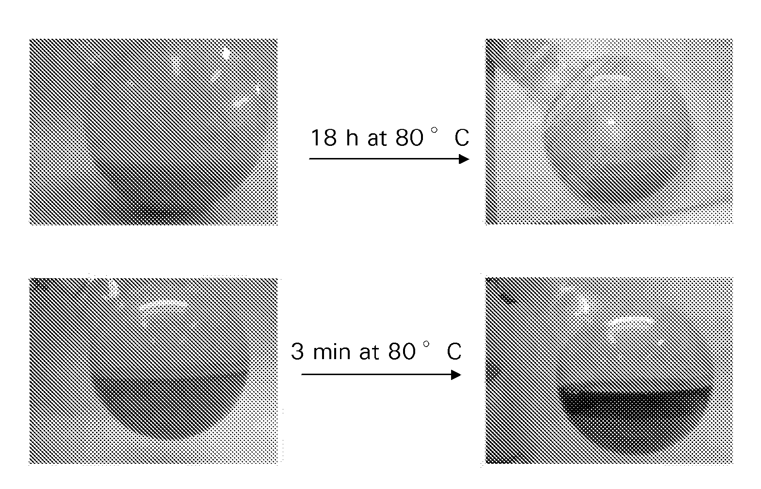
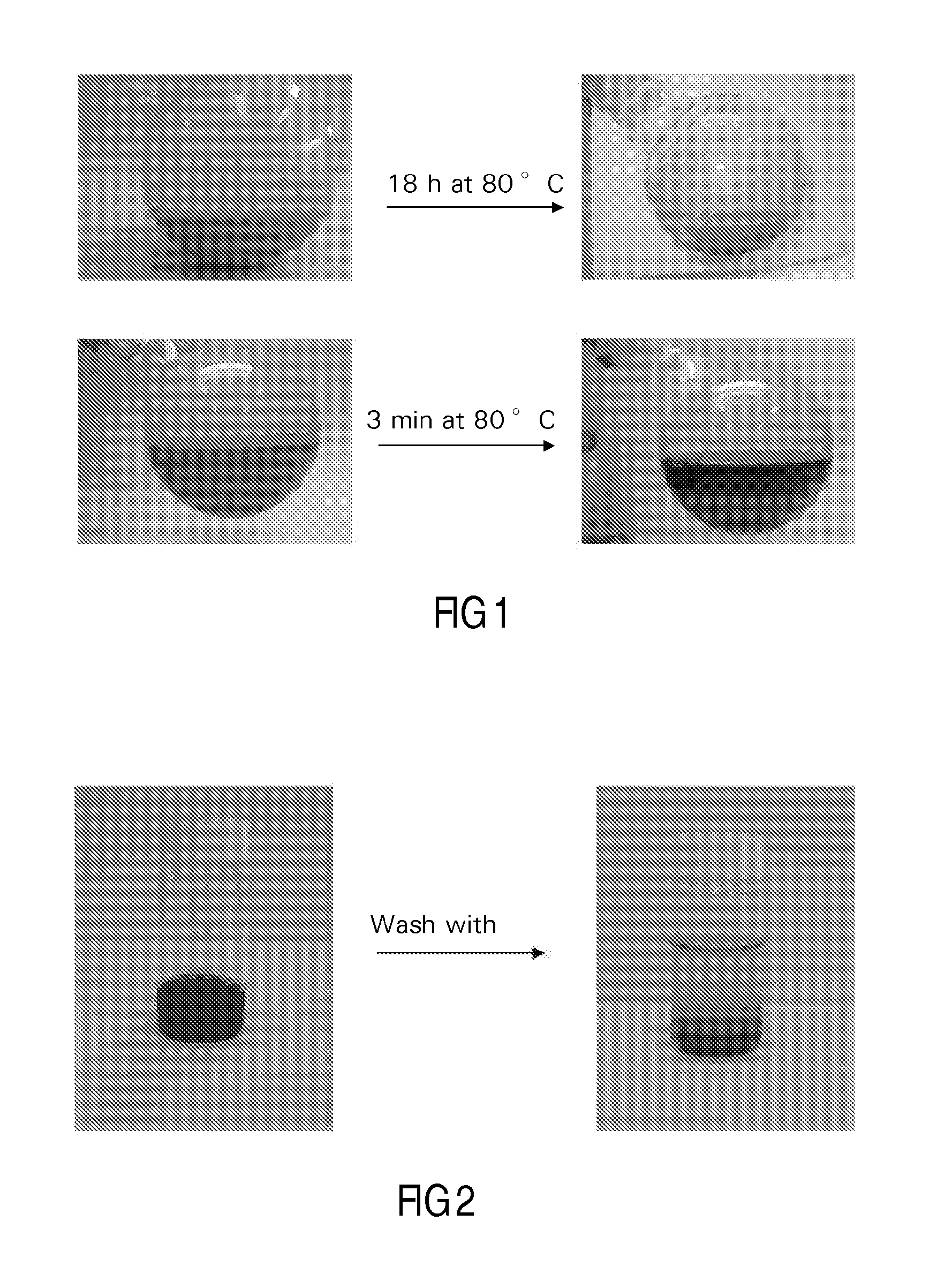
[0122]40 g of silica modified alumina was added to a suspension of 3.2 g of particulate cobalt hydroxide in 90 ml of water. The resulting mixture, which was in the form of a slurry, had a pH of 7.5. Aqueous slurry phase chemisorption was effected for 18 h at 80° C. During this process the pH slowly decreased to 5. The water layer was decanted from the mixture, and after three washings with water, the light purple colored product was dried at 40 mbar and 80° C. This vacuum dried treated catalyst precursor or intermediate was subjected to fluidized bed calcination, according to the following procedure using a continuous air flow of 1.6 dm3n / min, while increasing the t...

example 3

Co(OH)2 and Co(NO3)2 in Succession

Preparation of Inventive Catalyst 3

[0123]A 20 g Co / 0.070 g Pt / 100 g support catalyst was prepared on a particulate silica modified alumina support using sequential chemisorption-impregnation aqueous slurry phase preparation and drying, followed by direct fluidised bed calcination in air.

[0124]This preparation was done by means of two preparation steps: The first preparation step included chemisorption using cobalt hydroxide, while the second preparation step included impregnation using cobalt nitrate.

[0125]In particular, the catalyst was prepared as follows:

Cobalt Nitrate Solution

[0126]A cobalt nitrate solution was prepared using Co(NO3)2.6H2O and Pt(NH3)4.(NO3)2 resulting in a solution containing 140.2 g / l Co and 0.5328 g / l Pt. The pH of the solution was adjusted to 2.7 using nitric acid.

Chemisorption / Impregnation

[0127]40 g of silica modified alumina was added to 3.2 g of particulate cobalt hydroxide in 90 ml of water. The resulting suspension had ...

example 4

Co(OH)2 and Co(NO3)2 Simultaneously

Preparation of Inventive Catalyst 4

[0131]A 19.2 g Co / 0.070 g Pt / 100 g support catalyst was prepared on a particulate silica modified alumina support using simultaneous chemisorption-impregnation aqueous slurry phase preparation and drying, followed by direct fluidised bed calcination in air.

[0132]This preparation was done by means of a single preparation or processing step: The step included chemisorption using cobalt hydroxide and impregnation using cobalt nitrate. Thus, chemisorption and impregnation takes place in the same process step and is referred to as simultaneous chemisorption and impregnation.

[0133]In particular, the catalyst was prepared as follows:

Cobalt Nitrate Solution

[0134]A cobalt nitrate solution was prepared using Co(NO3)2.6H2O and Pt(NH3)4.(NO3)2 resulting in a solution containing 140.2 g / l Co and 0.5328 g / l Pt. The pH of the solution was adjusted to 2.7 using nitric acid.

Chemisorption / Impregnation

[0135]40 g of silica modified a...


PUM

PropertyMeasurementUnit
pressureaaaaaaaaaa
temperatureaaaaaaaaaa

Abstract

A process for preparing a catalyst precursor includes forming a slurry of particles of an insoluble metal compound, where the metal of the insoluble metal compound is an active catalyst component, with particles and / or one or more bodies of a pre-shaped catalyst support in a carrier liquid. The particles of the insoluble metal compound are thus contacted with the particles and / or the one or more bodies of the pre-shaped catalyst support. A treated catalyst support is thereby produced. Carrier liquid is removed from the slurry to obtain a dried treated catalyst support, which either directly constitutes the catalyst precursor, or is optionally calcined to obtain the catalyst precursor.

Description

FIELD OF THE INVENTION[0001]THIS INVENTION relates to catalysts. In particular, it relates to a process for preparing a catalyst precursor, and to a process for preparing a catalyst, which catalyst can be used, for example, in hydrogenation reactions, including hydrocarbon synthesis (for example Fischer-Tropsch (FT) synthesis) and including other hydrogenation reactions such as the hydrogenation of organic compounds.BACKGROUND ART[0002]Preparation of catalyst precursors by metal impregnation onto catalyst supports using various impregnation techniques is well known to those skilled in the art. The impregnated supports so obtained are then usually subjected to drying and calcination to provide catalyst precursors, and the precursors are then subjected to reduction to produce, finally, a catalyst.[0003]EP-A-0 736 326 describes cobalt impregnated alumina based Fischer-Tropsch synthesis catalysts synthesized by means of aqueous slurry phase impregnation of a cobalt salt, for example cob...

Claims


Application Information

Patent Timeline
Patent Type & Authority Patents(United States)
IPC IPC(8): B01J23/00C10G2/00B01J23/06B01J23/28B01J23/72B01J23/89B01J23/755B01J23/34B01J23/745B01J23/75B01J23/46B01J35/00B01J37/02B01J37/18C10G49/04C10G49/08
CPCB01J23/8986B01J23/06B01J23/28B01J23/34B01J23/462B01J23/72B01J23/745B01J23/75B01J23/755B01J23/892B01J23/8913B01J35/006B01J35/0013B01J37/0201B01J37/0205B01J37/0207B01J37/0219B01J37/18C10G2/332C10G2/334C10G49/04C10G49/08B01J35/393B01J35/45B01J2235/15B01J35/23
Inventor SANDEE, ALBERTUS JACOBUSTERORDE, ROBERT JOHAN ANDREAS MARIA
Owner SASOL TEKHNOLODZHI PROPRIEHJTEHRI LTD
Learn More