Power distribution device and assembling method thereof

a technology of power distribution device and assembly method, which is applied in the direction of electrical apparatus, server, support structure mounting, etc., can solve the problems of high manufacturing cost, complex assembly of the power distribution device, and inability to use it in large current transmission, etc., to achieve the effect of reducing the loss of current during transmission, and reducing the cost of manufacturing

Active Publication Date: 2017-01-03
LITE ON ELECTRONICS (GUANGZHOU) LTD +1
View PDF15 Cites 3 Cited by
  • Summary
  • Abstract
  • Description
  • Claims
  • Application Information

AI Technical Summary

Benefits of technology

[0010]Therefore, an object of this invention is to provide a power distribution device that can shorten a transmission path of current and that can reduce loss of current during transmission.
[0012]Yet another object of this invention is to provide a power distribution device that has a small size so as to effectively reduce an occupied space.
[0013]Still another object of this invention is to provide a power distribution device that can enhance heat dissipation effect.
[0015]Still yet another object of this invention is to provide an assembly method of a power distribution device that can permit easy and quick assembly to shorten the assembly time.
[0017]The efficiency of this invention resides in that because the first conductive terminals of each electrical connector are electrically connected to the signal control element, and the second conductive terminals of each electrical connector are electrically connected to the current transmission unit and the ground transmission unit, current outputted from each power supply unit can be supplied directly to the motherboard of the system through each electrical connector and the transmission mechanism. Through this, a transmission path of the current can be effectively shortened and loss of the current during transmission can also be reduced, so that the power distribution device can conduct large power and large current transmitting operation. Furthermore, because of the elongated structure and arrangement of the signal control element, the first conductive plate and the second conductive plate, and because of the arrangement and disposition of the electrical connectors on the signal control element, the first conductive plate and the second conductive plate, the space occupied by the power distribution device in the metal housing of the system can be minimized. Moreover, because the current transmission unit and the ground transmission unit of the transmission mechanism are made of metal conductive materials, the temperature will not easily rise during transmission of the current, so that the heat dissipation effect of the entire power distribution device is good. Additionally, because the assembling method of the electrical connectors with the signal control element, the current transmission unit and the ground transmission unit is easy and quick, the assembly time thereof is shortened.

Problems solved by technology

A high manufacturing cost will incur as a result.
Thus, the existing power distribution device 1 is not suitable for use in transmission of large current.
Moreover, since the existing power distribution device 1 has numerous components, the assembly thereof is complicated and consumes a lot of time.
Currently, application of cloud equipment is more and more extensive.
When the size and the number of the power supply unit disposed in an interior of the cloud equipment are increased, this will adversely affect an accommodation space of the power distribution device 1.

Method used


Image

  • Power distribution device and assembling method thereof
  • Power distribution device and assembling method thereof
  • Power distribution device and assembling method thereof

Examples


Embodiment Construction

[0033]Before the present invention is described in greater detail, it should be noted that like elements are denoted by the same reference numerals throughout the disclosure.

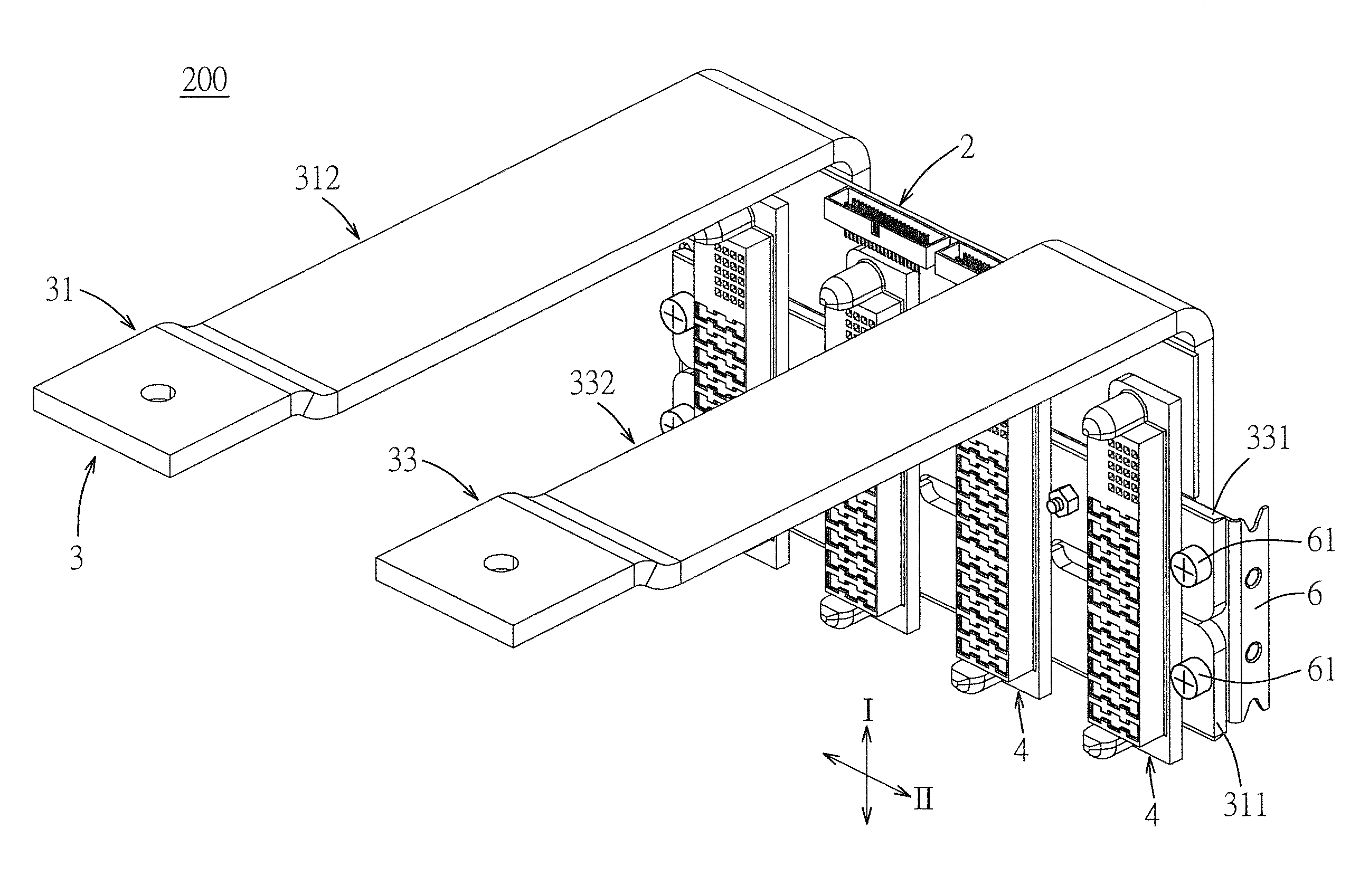
[0034]Referring to FIGS. 3 and 4, a power distribution device 200 according to the first preferred embodiment of the present invention is suitable for connection with a plurality of power supply units (not shown), and is shown to comprise a signal control element 2, a transmission mechanism 3 and a plurality of electrical connectors 4.

[0035]The transmission mechanism 3 includes a current transmission unit 31 and a ground transmission unit 33. Each of the current transmission unit 31 and the ground transmission unit 33 is made of a material having a conductive function. For example, the material may be a metal or other conductive material. In this embodiment, each of the current and ground transmission units 31, 33 is made of metal. The electrical connectors 4 are disposed on the signal control element 2 and the ...


PUM

PropertyMeasurementUnit
conductiveaaaaaaaaaa
currentaaaaaaaaaa
current conductiveaaaaaaaaaa

Abstract

A power distribution device for connection with a plurality of power supply units includes a signal control element, a transmission mechanism including a current transmission unit and a ground transmission unit, and a plurality of electrical connectors respectively adapted for insertion of and connection with the power supply units. Each electrical connector includes a first conductive terminals electrically connected to the signal control element for transmitting an electrical signal to the signal control element, and a plurality of second conductive terminals electrically connected to the current and ground transmission units for transmitting current to the current and ground transmission units.

Description

CROSS REFERENCE TO RELATED APPLICATION[0001]This application claims priority of Chinese Application No. 201310345203.X, filed on Aug. 8, 2013, the disclosure of which is incorporated herein by reference.BACKGROUND OF THE INVENTION[0002]1. Field of the Invention[0003]The invention relates to a power distribution device, and more particularly to a power distribution device for distributing current supplied by a power supply unit to a power distribution system and an assembling method thereof.[0004]2. Description of the Related Art[0005]Generally, a power distribution device is used for distributing current supplied by a power supply unit to a power distribution system for use according to the requirement thereof.[0006]Referring to FIGS. 1 and 2, an existing power distribution device 1 includes a casing 11, a motherboard 12 disposed in the casing 11, a circuit board 13 disposed in the casing 11 and spacedly below the motherboard 12, two conductive supports 14, two signal transmission e...

Claims


Application Information

Patent Timeline
Patent Type & Authority Patents(United States)
IPC IPC(8): H02B1/26H05K7/14H02B3/00
CPCH05K7/1492H02B1/26H05K7/1457Y10T29/49213
Inventor YU, KAI-KHUANYAO, NIEN-HUNGYANG, HSIN-YUKAO, YU-SHAN
Owner LITE ON ELECTRONICS (GUANGZHOU) LTD
Why Eureka
Try Eureka