Method and apparatus for additive manufacturing

a technology of additive manufacturing and manufacturing method, applied in the direction of additive manufacturing process, manufacturing tool, transportation and packaging, etc., can solve the problems of increasing the build time, high undesirable smoke of powder, and increasing the likelihood of stopping the additive manufacturing process

Active Publication Date: 2017-01-24
ARCAM AB
View PDF190 Cites 107 Cited by
  • Summary
  • Abstract
  • Description
  • Claims
  • Application Information

AI Technical Summary

Benefits of technology

[0008]An object of the various embodiments of the present invention is to provide a method and apparatus which may eliminate or at least reduce the above mentioned problem in the additive manufacturing process. The abovementioned object is achieved by the features in the method and apparatus claimed herein.
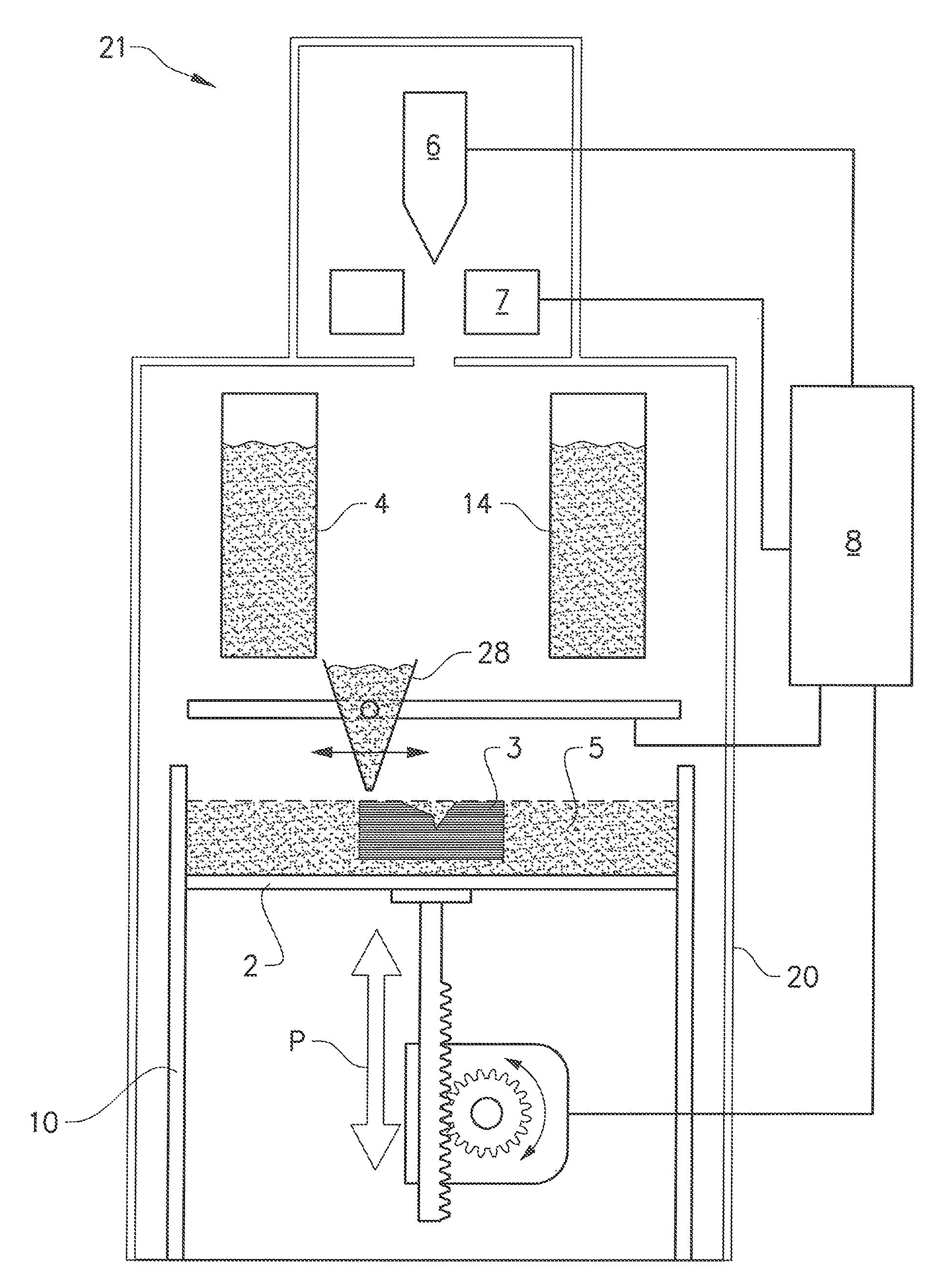
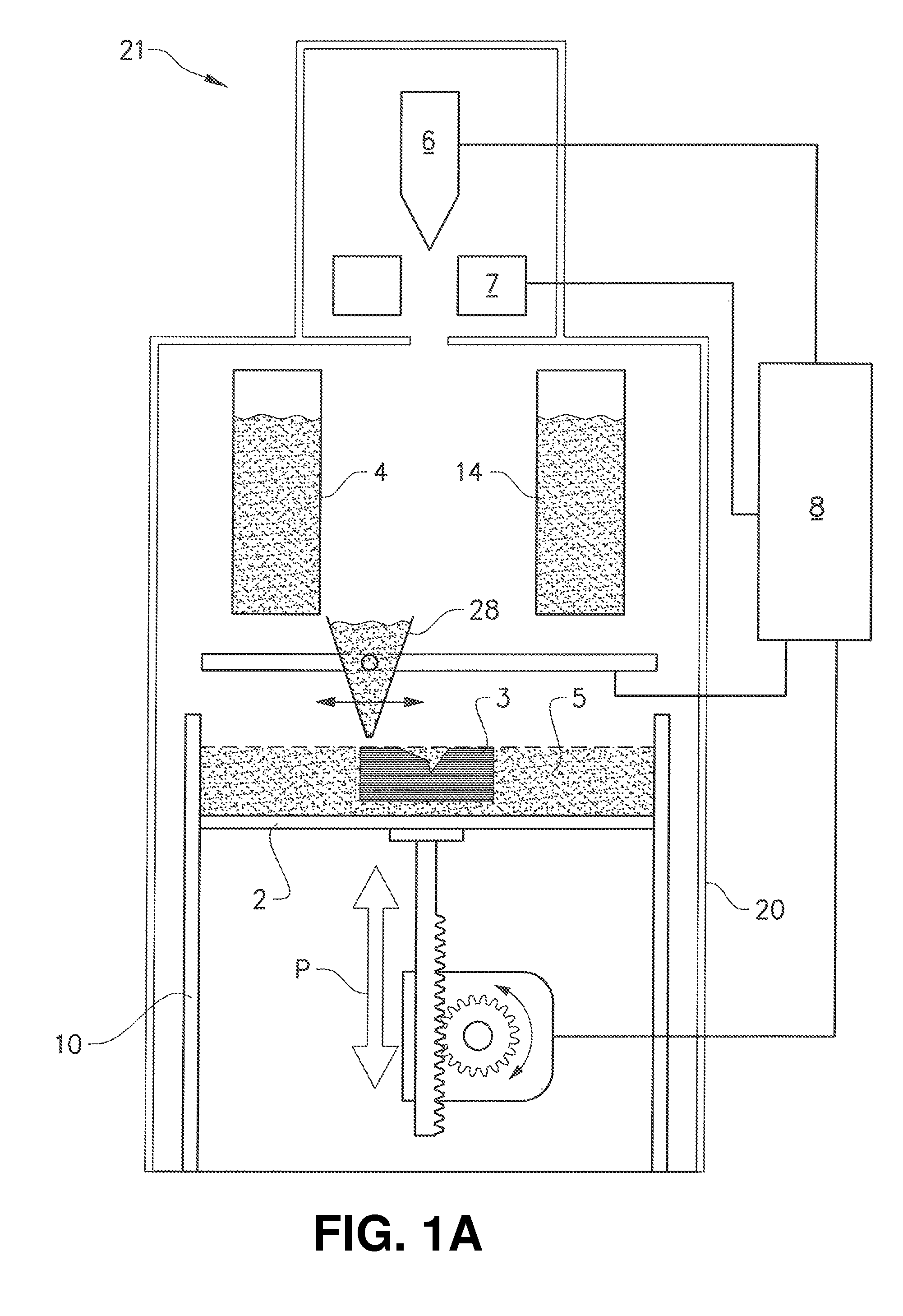
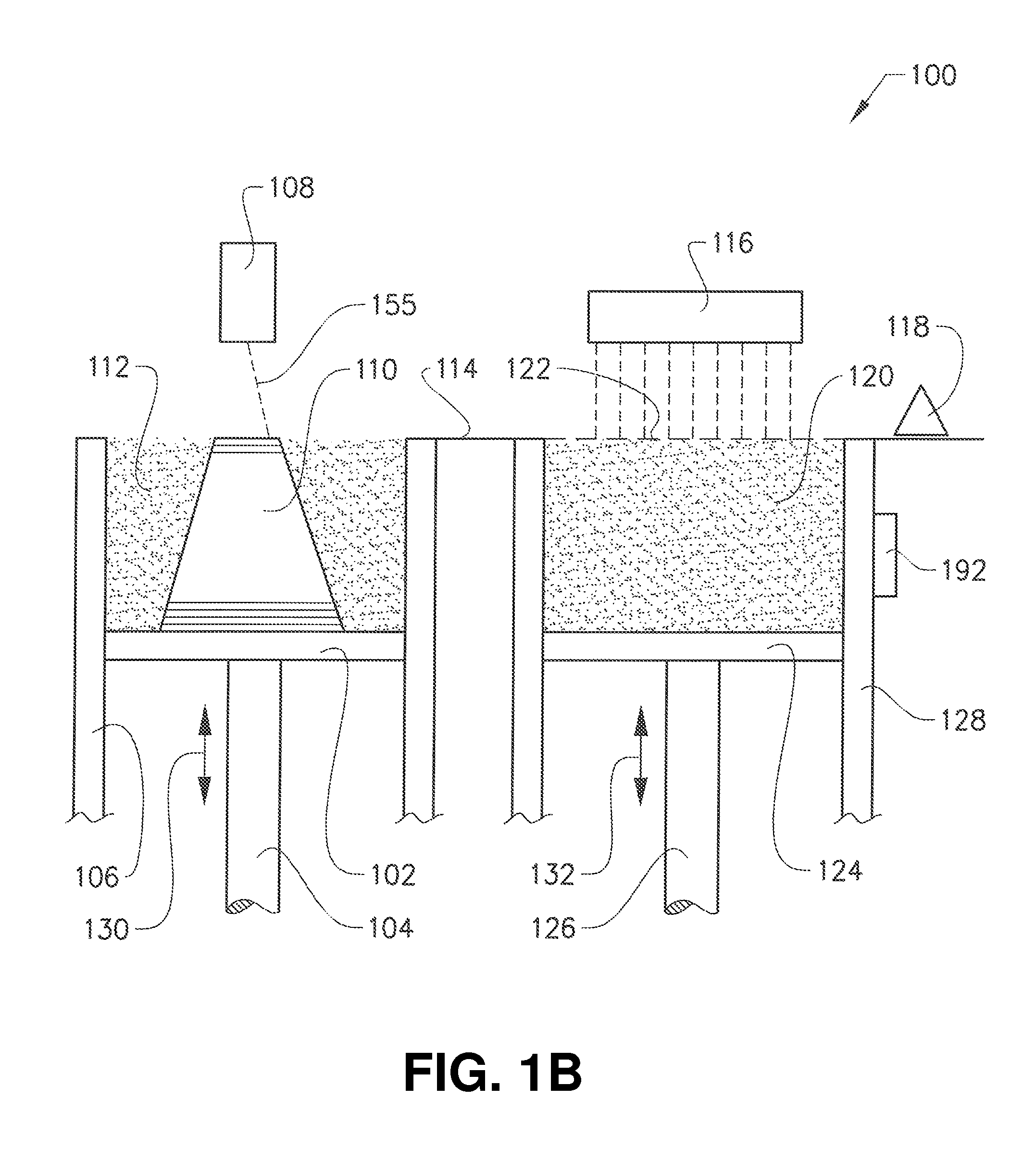
[0010]A non-limiting and exemplary advantage of various embodiments of the present invention is that the powder is coated in the vacuum chamber, i.e., the coating is performed under vacuum conditions, which means that the coated powder may be free of surface oxides. In an example embodiment the vacuum condition means a pressure which is less than 1×10⁻² mbar. In another example embodiment the vacuum condition means a pressure which is less than 1×10⁻³ mbar. Creating a coated powder without surface oxides means that the electrical conductivity of the powder is much higher compared to a pre coated powder which always has a thin layer of surface oxides and / or surface nitrides. Powder without surface oxides may be sintered at a lower temperature and faster compared to a powder which has surface oxides and / or surface nitrides. The increased conductivity of the powder also means that the probability of powder smoke may be greatly reduced.
[0011]In still other exemplary embodiments the coating is provided prior to providing the powder particles on the work table. The coating may for instance be provided on the top surface of the powder in the powder container which may be provided inside the vacuum chamber. The advantage of providing the coating prior to providing the powder on the work table where the three-dimensional article is to be manufactured in that coated and uncoated powder may be mixed during powder distribution on the powder table, which further may improve the electrical conductivity of the powder layer.
[0013]In still a further example embodiment of the present invention the work table may be vibrating while coating the powder on the work table. The advantage of vibrating the work table may be two fold, firstly the particles may rotate which means that a surface which is not visible for the coating device may be coated, secondly the particles may group together more homogenously, i.e., with less voids, thereby creating a better overall electrical conductivity and packing degree of the powder layer.

Problems solved by technology

Such “smoke” of powder is highly undesirable because, if it happens, the additive manufacturing process is most likely to be stopped.
These methods may increase the build time which may be a problem.

Method used


Image

  • Method and apparatus for additive manufacturing
  • Method and apparatus for additive manufacturing
  • Method and apparatus for additive manufacturing

Examples


Embodiment Construction

[0025]To facilitate the understanding of various embodiments of the present invention, a number of terms are defined below. Terms defined herein have meanings as commonly understood by a person of ordinary skill in the areas relevant to the present invention. Terms such as “a”, “an” and “the” are not intended to refer to only a singular entity, but include the general class of which a specific example may be used for illustration. The terminology herein is used to describe specific embodiments of the invention, but their usage does not delimit the invention, except as outlined in the claims.

[0026]The term “three-dimensional structures” and the like as used herein refer generally to intended or actually fabricated three-dimensional configurations (e.g. of structural material or materials) that are intended to be used for a particular purpose. Such structures, etc. may, for example, be designed with the aid of a three-dimensional CAD system.

[0027]The term “electron beam” as used herei...


PUM

PropertyMeasurementUnit
pressureaaaaaaaaaa
pressureaaaaaaaaaa
thicknessaaaaaaaaaa

Abstract

Various embodiments provide a method and apparatus for forming a three-dimensional article through successive fusion of parts of at least one layer of a powder bed provided on a work table in an additive manufacturing machine, which parts corresponds to successive cross sections of the three-dimensional article. The method comprises the steps of: applying a layer of predetermined thickness of powder particles on the work table, applying a coating on at least a portion of the powder particles, which coating is at least partially covering the powder particles, and fusing the powder particles on the work table with an electron beam.

Description

CROSS-REFERENCE TO RELATED APPLICATIONS[0001]This application claims priority to and the benefit of U.S. Provisional Patent Application Ser. No. 61 / 813,555, filed Apr. 18, 2013, the contents of which are hereby incorporated by reference in their entirety.BACKGROUND[0002]Technical Field[0003]The present invention relates to a method and an apparatus for additive manufacturing.[0004]Description of Related Art[0005]Freeform fabrication or additive manufacturing is a method for forming three-dimensional articles through successive fusion of chosen parts of powder layers applied to a worktable.[0006]An additive manufacturing apparatus may comprise a work table on which the three-dimensional article is to be formed, a powder dispenser, arranged to lay down a thin layer of powder on the work table for the formation of a powder bed, an energy beam for delivering energy to the powder whereby fusion of the powder takes place, elements for control of the energy given off by the energy beam ove...

Claims


Application Information

Patent Timeline
Patent Type & Authority Patents(United States)
IPC IPC(8): B05D3/06C23C14/00B29C67/00C23C16/44C23C14/22B28B1/00B22F1/02B22F3/105B22F1/18
CPCB05D3/068B22F1/025B22F3/1055B28B1/001B29C67/0077C23C14/00C23C14/223C23C16/4417B22F2003/1056B22F2998/10B22F2999/00Y02P10/295C23C16/00B22F2202/01B29C64/153Y02P10/25B22F12/49B22F12/55B22F10/32B22F12/52B22F10/36B22F10/28B33Y70/00B22F1/18B22F10/20B33Y10/00B33Y30/00
Inventor ACKELID, ULF
Owner ARCAM AB
Why Eureka
Try Eureka