
Barrel and an electromagnetic projectile launching system

a launcher and electromagnetic technology, applied in the field of electromagnetic launcher rails, can solve the problems of rendering the gun useless after, and achieve the effects of improving the behavior of the gun, elasticity and flexibility, and increasing velocity

Inactive Publication Date: 2017-01-24
SIERRA IZQUIERDO BORJA
View PDF14 Cites 3 Cited by
  • Summary
  • Abstract
  • Description
  • Claims
  • Application Information

AI Technical Summary

Benefits of technology

The invention relates to improving the durability and performance of electromagnetic launcher rails for launching a projectile at high speed using copper rails. The patent proposes the use of a graphene layer over the copper rails to enhance the use of general electromagnetic launchers. The graphene layer has excellent electrical conductivity and the absence of a resistivity band, which improves the way the armature is fired. It also helps in preventing erosion caused by the release of the electrical discharge and the friction inside the barrel. The use of twisted graphene rails and the implementation of proper rifling into the bore allows for a greater stability and reach of the payload. Heating effects are a major concern in every gun, and the high electrical conductivity and lack of resistivity band in graphene improve the efficiency and consumption of electricity. The invention also provides a projectile enhancement with the use of graphene as a protective layer. The deviation of the magnetic field can be used to spin the projectile inside the barrel while avoiding the use of external coils and improving stability and reach. Different layers of shielding should be arranged to add their effect to the overall effort.

Problems solved by technology

Mainly, these problems deal with the huge erosion the rails suffer, rendering the gun useless after just a few shots.
Some proposals have directed the subject towards the use of super conductive magnets, but at the expense of needing an unpractical liquid nitrogen refrigerated gun for those purposes.

Method used


Image

  • Barrel and an electromagnetic projectile launching system
  • Barrel and an electromagnetic projectile launching system
  • Barrel and an electromagnetic projectile launching system

Examples


Embodiment Construction

[0030]In connection with the figures, several examples of embodiments of the invention are further detailed. The examples are shown simply by a way of illustration and will be regarded not as restrictive of the invention scope.

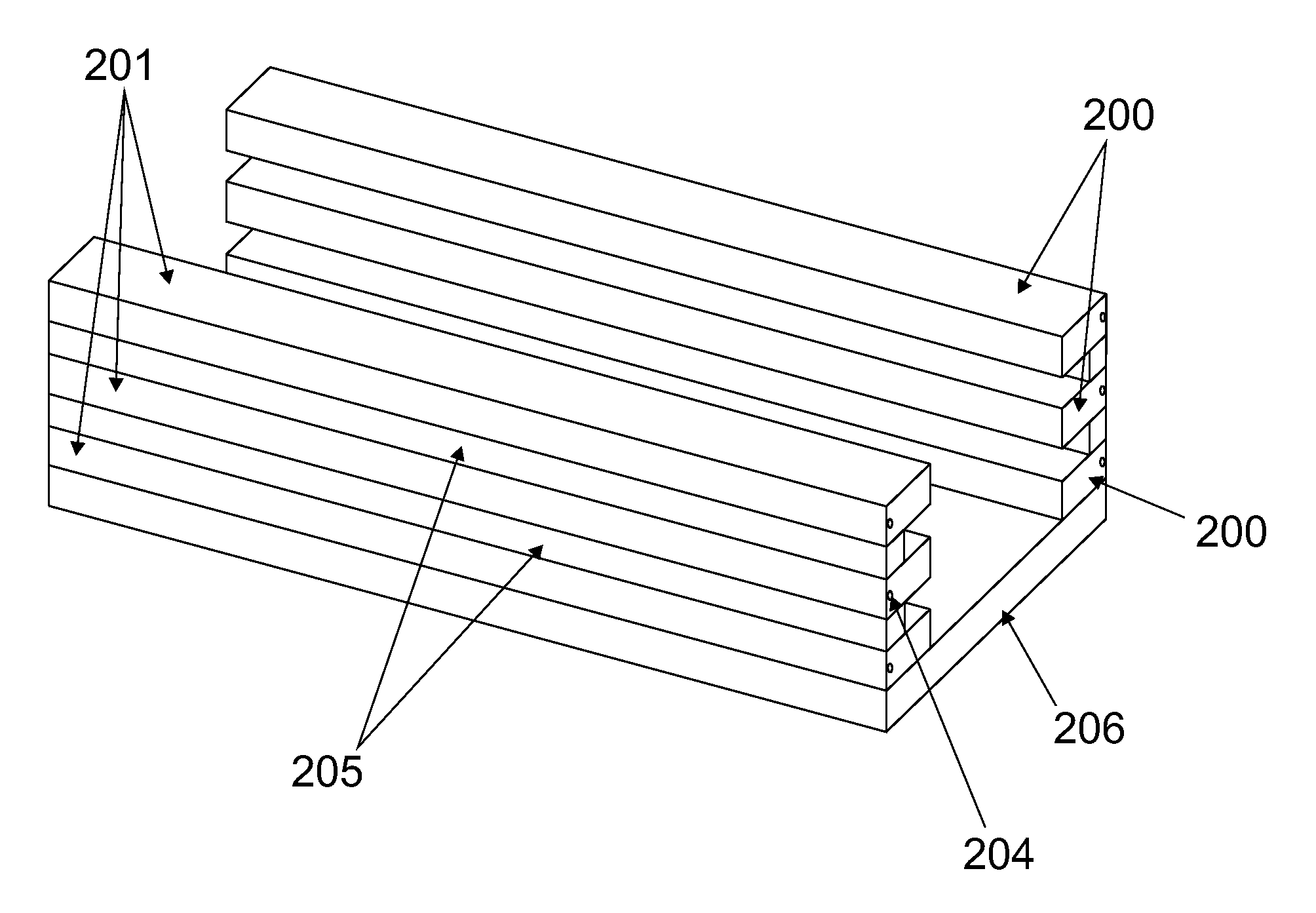
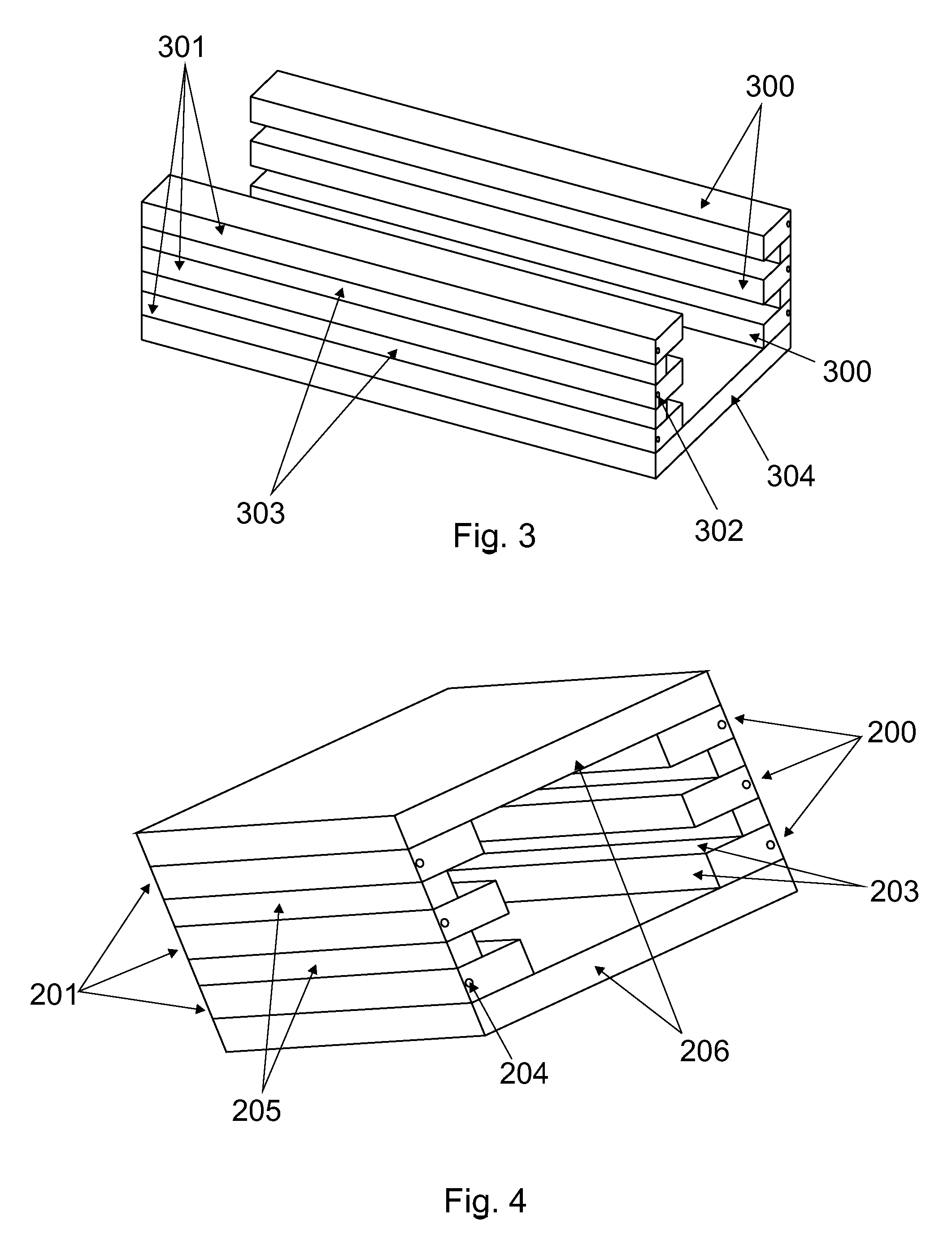
[0031]The present invention is an electromagnetic projectile launching system which uses a plurality of conducting rails assembled in pairs, to accelerate conductive armatures.

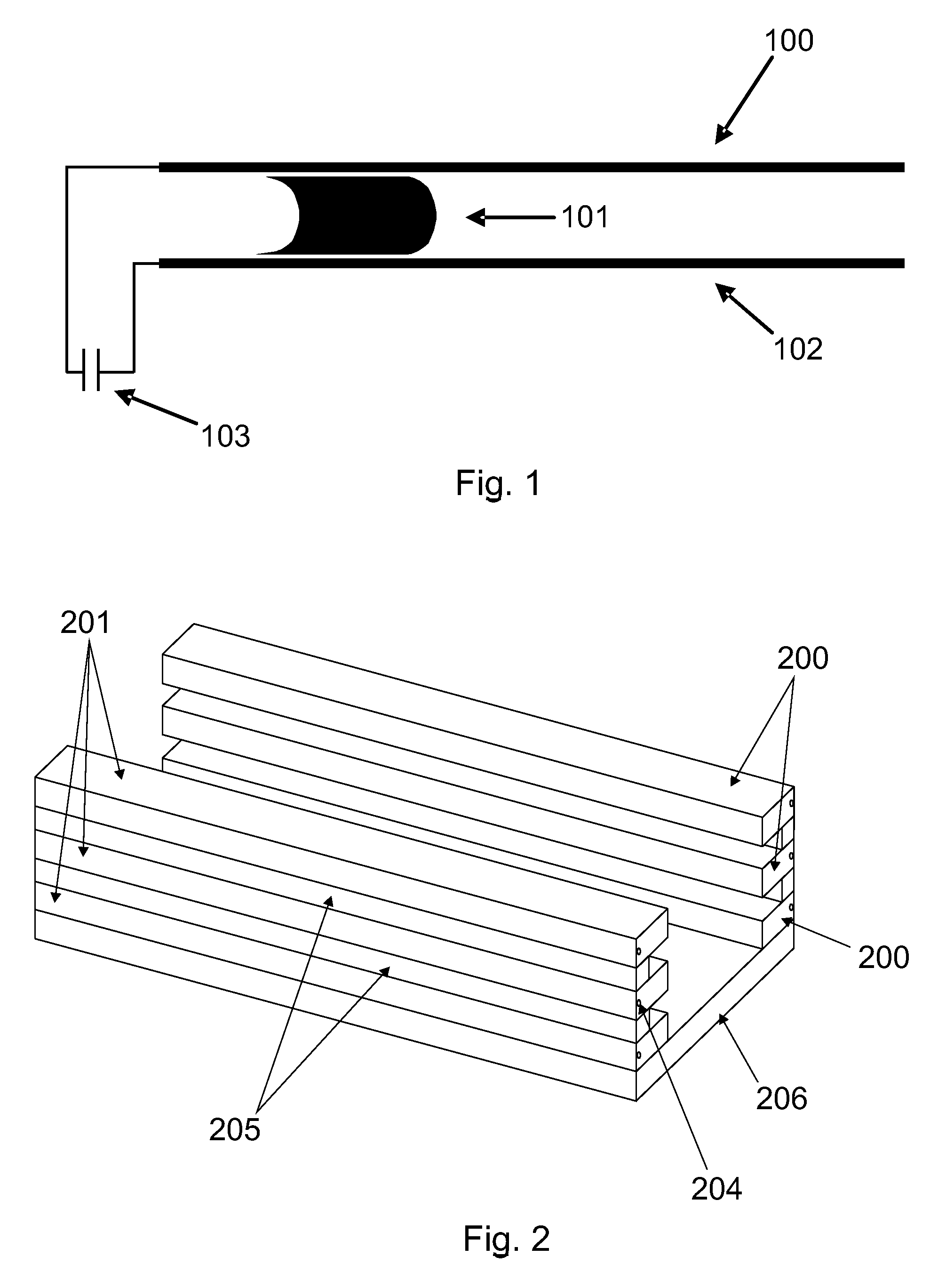
[0032]FIG. 1 is a schematic illustration of an electromagnetic rail gun. The rail gun of FIG. 1 uses a positive rail 100, a sliding armature 101, and a negative rail 102. As illustrated in FIG. 1, a high current I from a generator (AC or DC) 103 enters the positive rail 100, and is conducted through the sliding armature 101 and negative rail 102 to produce a strong magnetic field which drives the sliding armature 101 forward. Those skilled in the art will know that a plurality of pairs 100-102 can be used with advantage, and here both will appear along the description. In that case, one ...


PUM


Abstract

A multiple rails magnetic accelerator is presented. By means of an electric discharge, a magnetic field is created which moves an armature along the rails. These rails are made in such way they can stand multiple shoots without eroding. The launcher is configured such that the critical velocity of the armature increases along the axial direction towards the muzzle as it moves through the gun. The rails are separated with a proper electrical insulator and the whole structure can be surrounded by one or more shells to confine the barrel and apply compressive stress. The compressive stresses applied preload the rails and the composite barrel structure to resist overall forces encountered during projectile firing.

Description

FIELD OF INVENTION[0001]The invention relates generally to electromagnetic launcher rails, and more particularly to such methods and configurations that preferably can improve durability and performance of rails for launching a projectile at high speed (in the order of 3-7 km / s) or hypervelocities (in the order of >10 km / s).STATE OF THE ART[0002]Electromagnetic rail guns (EMG) have attracted much attention for the last years; its applications fields include mining, military, hunting and sports guns, drone launching, transport, nuclear power stations and missile / rocket launching among others. But it is recently that their research has reached a mature state and industrial development starts.[0003]Previous attempts have been made since 1921 (U.S. Pat. No. 1,985,254) along multiple approaches to the problems these type of inventions present. Mainly, these problems deal with the huge erosion the rails suffer, rendering the gun useless after just a few shots. Some proposals have direc...

Claims


Application Information

Patent Timeline
Patent Type & Authority Patents(United States)
IPC IPC(8): F41B6/00F42B6/00
CPCF41B6/006F42B6/006
Inventor SIERRA IZQUIERDO, BORJA
Owner SIERRA IZQUIERDO BORJA
Learn More