Deep hole machining on-line deviating correction device based on laser detection

Active Publication Date: 2017-02-07
ZHONGBEI UNIV
View PDF10 Cites 1 Cited by
  • Summary
  • Abstract
  • Description
  • Claims
  • Application Information

AI Technical Summary

Benefits of technology

[0013]The disclosure provides advantages of ensuring good straightness and position accuracy of the machined deep hole. Specifically, the advantages includes: Firstly, the laser transmitter and the photosensitive sensor are positioned on the outer frame, such that high temperature generated during the machining process is avoided from affecting the laser transmitter and the sensor. If one of the laser transmitter and the photosensitive sensor were to be positioned within the hole, it would be difficult to achieve the detection effect due to the generated high temperature. The disclosure takes full advantage of the parallel reflection of the laser beam produced by the pyramid prism to achieve the aforementioned effect. Secondly, by means of observing the graphics displayed on the computer, the position variation of the deep hole cutter is detected on line and thus the working conditions of the workpiece rotation and the deep cutter feeding during the machining process are obtained in time. Since the position variation of the deep hole cutter indirectly reflects the hole

Problems solved by technology

Some of these holes require high machining accuracy and surface quality, and sometime the materials to be machined have poor machinability.
All the above methods is incapable of detecting the axis deviation inside the deep hole, such that a continuous dynamic detection on the straightness of the deep hole part is not achieved and therefore inaccuracy occurs.

Method used


Image

  • Deep hole machining on-line deviating correction device based on laser detection
  • Deep hole machining on-line deviating correction device based on laser detection
  • Deep hole machining on-line deviating correction device based on laser detection

Examples


Embodiment Construction

[0019]The embodiments of the disclosure may be described below in detail with reference to accompanying drawings. These embodiments should be construed as describing the disclosure, but not for limiting the scope of the disclosure.

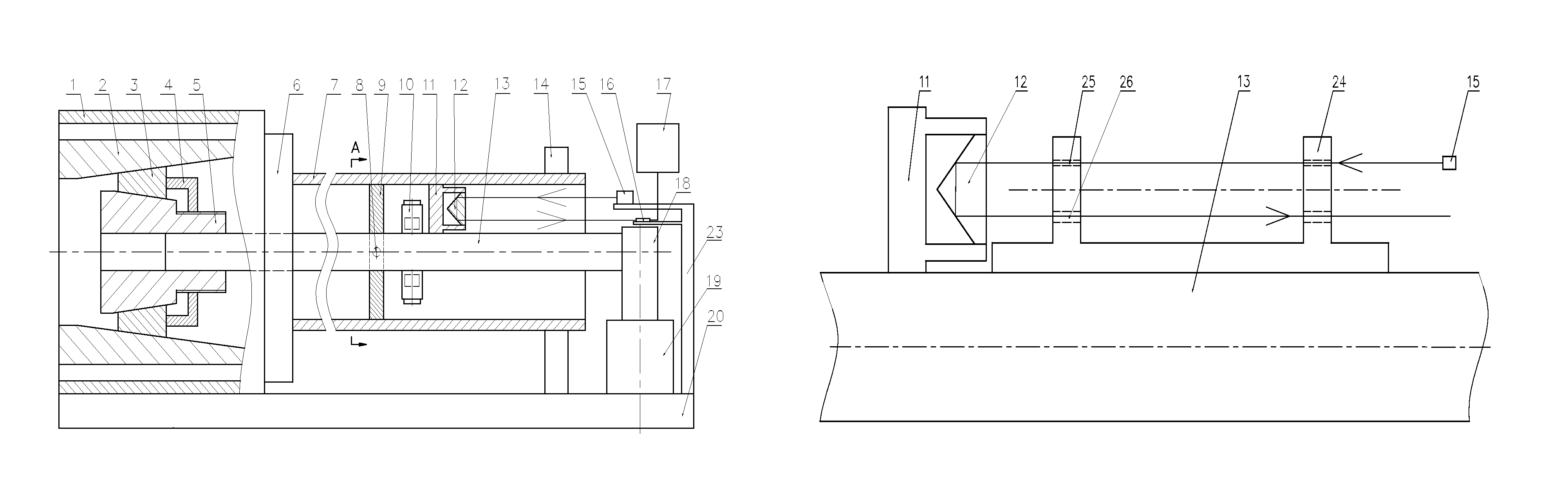
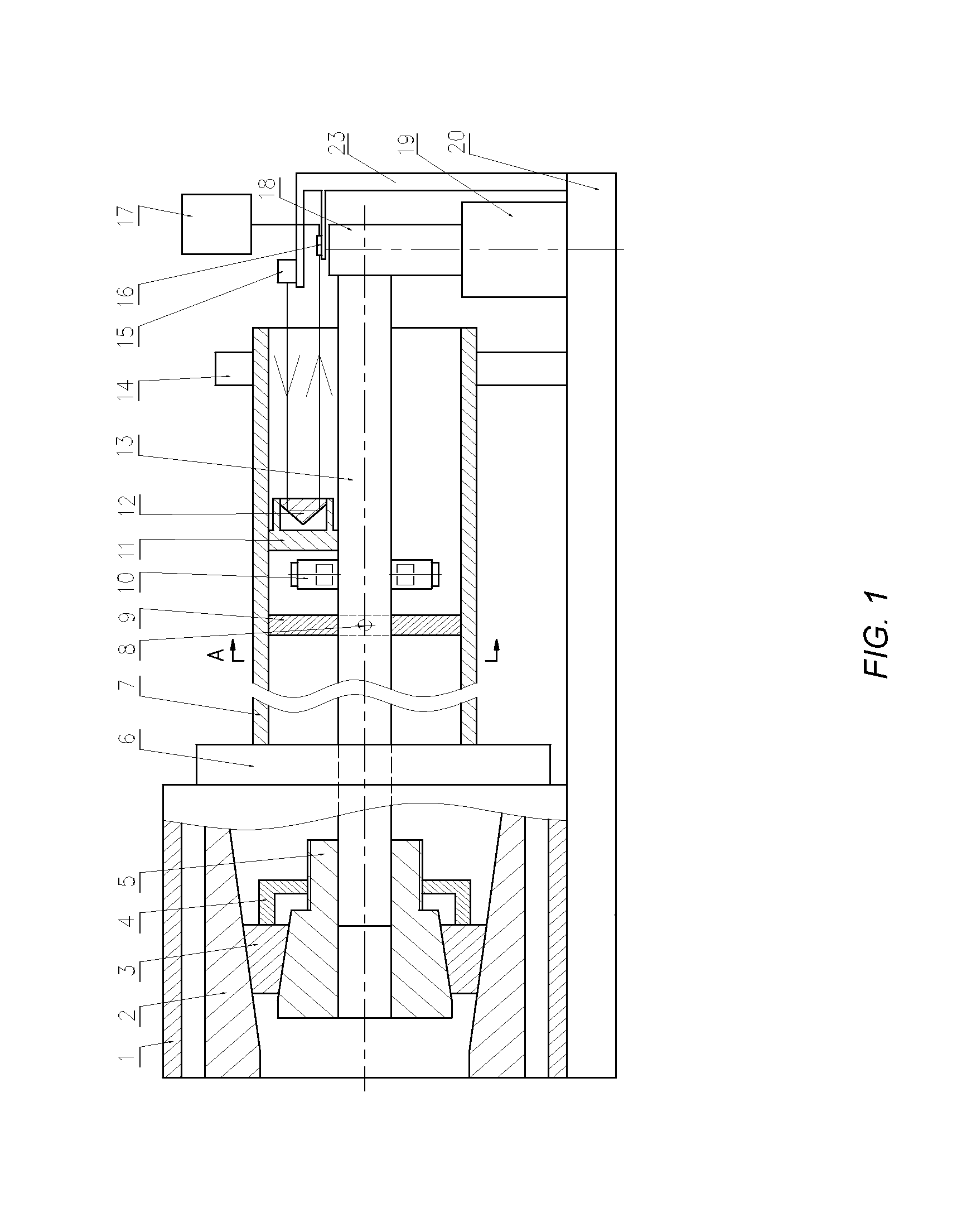
[0020]In the first embodiment, as shown in FIGS. 1-3, a workpiece 7 rotates and a deep hole cutter 9 feeds. The workpiece 7 is provided with a bottom hole, and a deep hole with a horizontal axis is to be machined.

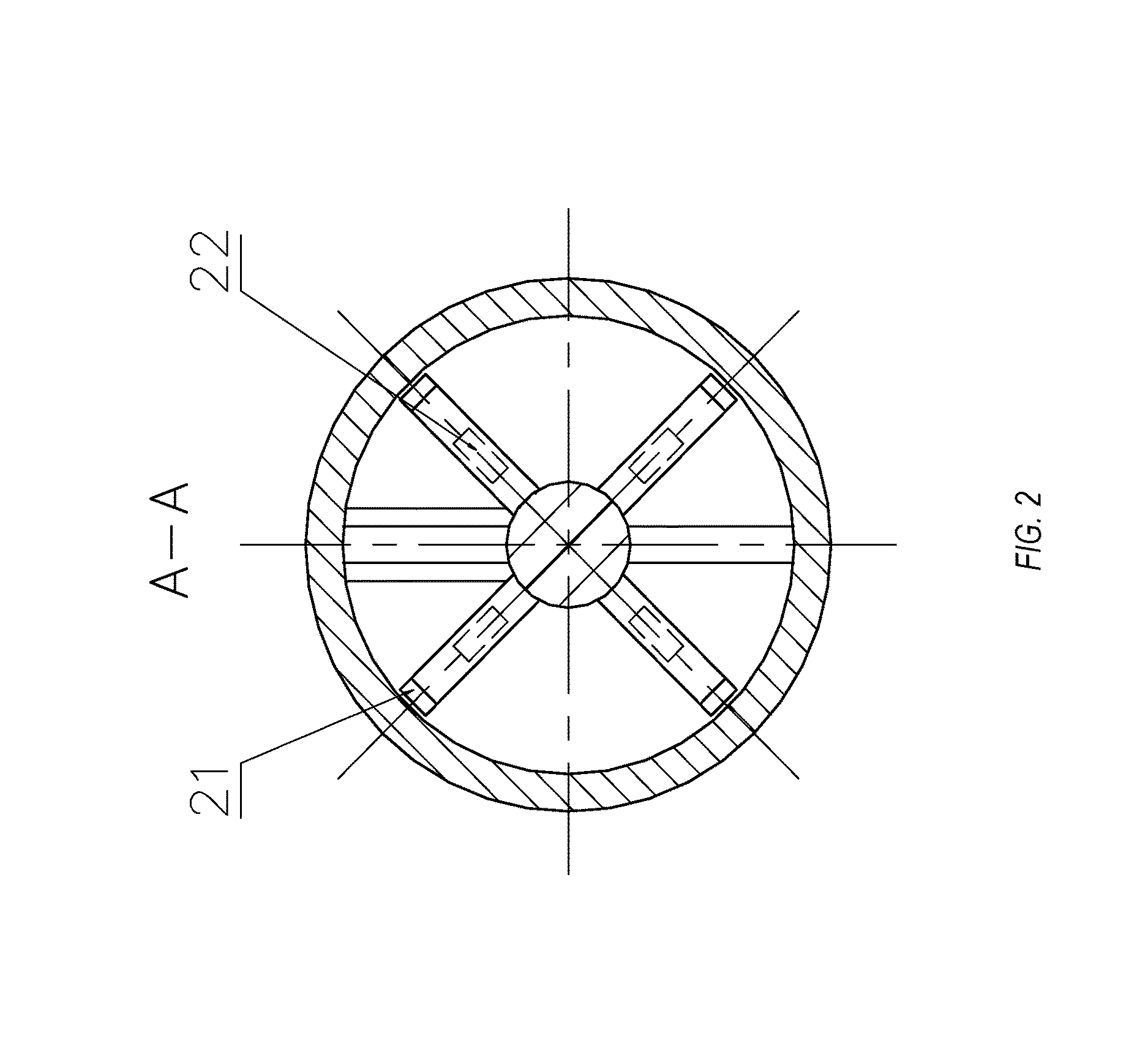
[0021]In the disclosure, provided are a deep hole cutter 9, a cutter bar 13, a spindle box 1, a spindle 2, an expansion bushing 3, a retaining nut 4, a core sleeve 5, a clamper 6, a fastening screw 8, a metallic block 10, a pyramid prism seat 11, a pyramid prism 12, a center support 14, a laser transmitter 15, a photosensitive sensor 16, a computer 17, a cutter bar support 18, a slide plate 19, a machine tool bed 20, a wear / heat-resistant block 21, a heating device 22, an outer frame 23, a laser orientating block 24 and the like. The deep hole is ...


PUM

PropertyMeasurementUnit
Electrical resistanceaaaaaaaaaa
Photosensitivityaaaaaaaaaa

Abstract

The disclosure relates to a technical field of deep hole machining, particularly to a deep hole machining on-line deviating correction device based on laser detection, which solves the prior art problem of difficulty in the real-time, on-line detection and deviating correction in the process of deep hole machining. The device comprises a deep hole cutter and a cutter bar, and arranged on the cutter bar are a laser orientating block, a pyramid prism seat, the deep hole cutter and a metallic block with a heating device arranged therein. A beam emitted by a laser transmitter is orientated by the laser orientating block so as to be incident in parallel with the axis of the cutter bar, and then through a pyramid prism to form a return beam which reaches the photosensitive sensor. The advantages of the disclosure lie in that skewing of the deep hole cutter can be detected in time and skewing correction of the deep hole tool is achieved based on the heat expansion and cold contraction mechanism, and therefore the straightness and position accuracy during deep hole machining are improved.

Description

RELATED APPLICATIONS[0001]The present application claims priority to China Patent Application Serial No. CN 201510774720.8 filed on Nov. 13, 2015, which is hereby incorporated by reference in its entirety.TECHNICAL FIELD[0002]The disclosure relates to the technical field of deep hole machining, particularly to a deep hole machining on-line deviating correction device based on laser detection.BACKGROUND[0003]The term “deep hole” relates to a hole having a ratio of a hole length to a hole diameter that is greater than 5, such as a hollow spindle hole and a hydraulic valve hole. Some of these holes require high machining accuracy and surface quality, and sometime the materials to be machined have poor machinability. In the process of the deep hole machining, the operator is not able to directly inspect the conditions of the machined part and the cutter, but has to listen to the sound of cutting, observe the conditions of chips, tactually feel the vibration condition and the temperature...

Claims


Application Information

Patent Timeline
IPC IPC(8): B23K26/00G01S17/42B23B41/02B23B29/02
CPCB23B41/02B23B29/027G01S17/42B23B2260/092B23B2260/128B23B29/02
Inventor YU, DAGUOSHEN, XINGQUANLI, YANLANHUANG, XIAOBINWANG, CHUANGMINBO, XIAOMINGQUAN, BAOLUODONG, ZHEN
Owner ZHONGBEI UNIV
Why Eureka
Try Eureka