Counter-flow membrane plate exchanger and method of making

a technology of counter-flow membrane and exchanger, which is applied in the direction of indirect heat exchangers, stationary plate conduit assemblies, lighting and heating apparatus, etc., can solve the problems of material waste during manufacturing, incompatibility of existing plate-type exchangers, and increased end-use costs of exchangers, so as to reduce construction time, improve the effect of sealing characteristics and superior results in pressurized crossover leakag

Active Publication Date: 2017-02-07
ENERGY WALL
View PDF10 Cites 10 Cited by
  • Summary
  • Abstract
  • Description
  • Claims
  • Application Information

AI Technical Summary

Benefits of technology

[0033]An embodiment of a heat and water vapor exchanger, for transferring heat and vapor between a first fluid stream and a second fluid stream, the exchanger comprising: a housing with a first surface containing a first plurality of inlet ports and outlet ports, and a substantially parallel opposing second surface containing a second plurality of inlet ports and outlet ports. The first inlet ports on first surface are directly opposite second inlet ports on second surface and first outlet ports on first surface are directly opposite second outlet ports on second surface. A counter-pleated core is generally enclosed within a housing. The core comprises multiple layers of folded, water-permeable membrane material defining a stack of alternating first and second fluid passageways, wherein each layer comprises a portion of at least two strips of said water-permeable membrane material joined by one seam for a first pair of two strips and one additional seam for each additional strip. The seams joining membrane strips are subsequently internal within counter-pleated core and substantially parallel to a direction of general airflow movement. The folds of water-permeable membranes define inlet and outlet ports on first and second faces of counter-pleated core and being substantially perpendicular to seam(s). All first inlets on first face fluidly connect to all second outlets on second face and wherein all second inlets on the second face fluidly connect to all first outlets on the first face. Exchangers utilizing counter-pleated membranes and cross-pleated separators of the type described herein have enhanced sealing characteristics and reduced construction time. ERV cores comprising counter-pleated cores of this type described herein have given superior results in pressurized crossover leakage relative to conventional planar plate-type core designs. ERV cores comprising counter-pleated cores of this type described herein have given superior results in moisture transfer relative to conventional planar plate-type core designs.
[0034]Exchangers utilizing counter-pleated membranes and cross-pleated spacers of the type described herein have improved heat and / or moisture transfer efficiencies.
[0035]Exchangers utilizing counter-pleated membranes and cross-pleated spacers of the type described herein have reduced material costs and reduced construction time.
[0036]Exchangers utilizing counter-flow exchanger and related manifolding described herein utilize less depth, less volume, and are overall more compact to fit into existing HVAC equipment.
[0037]Exchangers utilizing this folding configuration are advantageous in that they reduce the number of edges that have to be sealed, especially relative to counter-flow plate-type heat and water vapor exchangers where individual pieces of membrane are stacked and have to be sealed along four edges.

Problems solved by technology

An energy recovery wheel typically exhibits high heat and moisture transfer efficiencies, but has undesirable characteristics including a fast rotating mass inertia (1-3 seconds per revolution), a high cross-contamination rate, high pollutant and odor carryover, a higher outdoor air correction factor than is ideal, a need for an electrical energy supply to power geared drive motors, and a need for frequent maintenance of belts and pulleys.
However, any efficiency gained in this manner is offset by more negative effect of the undesirable characteristics here noted.
A further disadvantage is the incompatibility of existing plate-type exchangers to fit into existing air handling units designed to accommodate the relatively thin depth profiles of energy recovery wheels prohibiting retrofit replacement of a wheel by a typical plate-type exchanger.
The need for customization increases the end-use cost of the exchangers, material waste during manufacturing, design time, failure-testing costs, and a number of performance verification certifications.
In some HVAC systems, use of an energy recovery wheel may be prohibited due to the inherent risk of failure of the motor, belts, and seals.
Plate-type energy exchanger designs utilize a large number of joints and edges that need to be sealed; consequently, the manufacturing of such devices can be labor intensive as well as expensive.
The durability of plate-type energy exchangers can be limited, with potential delaminating of the membrane from the frame and failure of the seals, resulting in leaks, poor performance, and cross-over contamination (leakage between streams).
However, the flow configurations that are achievable with concertina-style pleated membrane cores are limited, and there is still typically a need for substantial edge sealing, such as potting edges in a resin material.
Another disadvantage is the higher pressure drop as a result of the often smaller size of the entrance and exit areas to the pleated core.
Some current counter-flow plate type arrangements have achieved heat transfer efficiencies equal to or greater than energy recovery wheels, but incur the penalties of a much greater volume, higher pressure drop, and higher cost when compared to a recovery wheel.
In addition, current counter-flow plate designs generally transfer thermal energy only.
Counter-flow heat and moisture plate-type exchangers have been expensive to produce due to inherent difficulty of the plate separation techniques, plate sealing, and inefficient use of materials.
Attempts to increase vapor transmission have employed very expensive and specialized polymeric membranes, and have not seen wide spread practical use.
This is partially due to spacer materials and membrane seam bonding that are impermeable to water vapor, effectively reducing the available surface area for water transport.
Thus, spacing techniques blocking the effective surface area of one side of the membrane inherently inhibits the vapor transmission on the opposite side of the membrane.

Method used


Image

  • Counter-flow membrane plate exchanger and method of making
  • Counter-flow membrane plate exchanger and method of making
  • Counter-flow membrane plate exchanger and method of making

Examples


Embodiment Construction

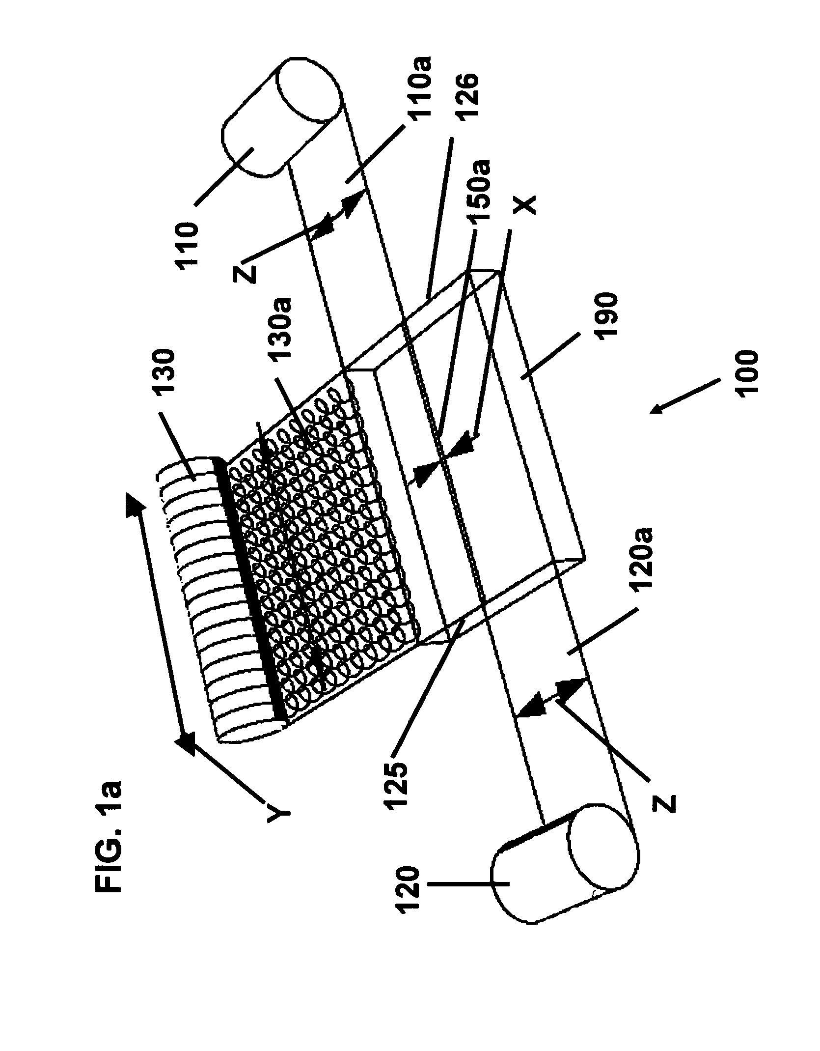
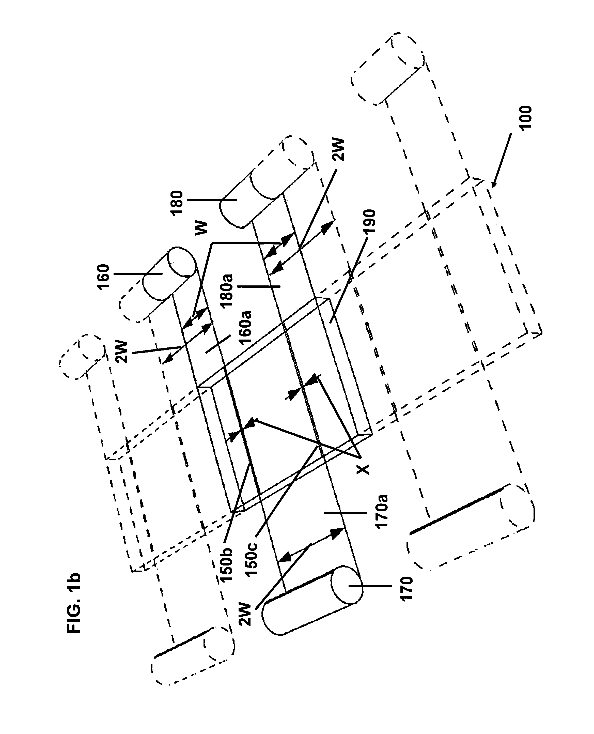
[0046]FIGS. 1a-b show simplified schematic diagrams illustrating a variety of starting positions and starting number of membrane strips that can be utilized to make a counter-pleated, counter-flow core 100. In FIG. 1a two strips of membrane 110a and 120a of width Z are drawn in substantially opposite directions from two reels of membrane, 110 and 120, respectively. Start of membrane 110a is produced by 90° angle cut 125. Start of membrane 120a is produced by 90° angle cut 126. Membrane strips 110a and 120a are arranged edge-to-edge in the same plane on the top surface of a base frame or platform 190. The resultant seam 150a forms an overlap of X distance. One strip of separator 130a is drawn at a 90° angle to strips 110a and 120a from reel of separator 130 of width Y. FIG. 1b illustrates a repeating pattern to start construction of a counter-pleated core 100. Three or more strips of membrane 160a, 170a, and 180a of width W or 2W are drawn in substantially opposite directions from tw...


PUM

PropertyMeasurementUnit
90° angleaaaaaaaaaa
anglesaaaaaaaaaa
thermal energyaaaaaaaaaa

Abstract

A counter-flow plate type exchanger is manufactured by repeatedly folding and joining at least two strips of membrane to form a counter-pleated core with a stack of openings or fluid passageways configured in an alternating counter-flow arrangement. Methods for manufacturing such counter-pleated cores are described. Counter-pleated cores comprising water-permeable membranes can be used in a variety of applications, including heat and water vapor exchangers. In particular, they can be incorporated into energy recovery ventilators (ERVs) for exchanging heat and water vapor between air streams directed into and out of buildings, automobiles, or other Industrial processes.

Description

FIELD OF THE INVENTION[0001]The present invention relates to counter-pleated membrane plate exchangers and cross-pleated membrane spacers. More particularly the invention relates to exchangers in which the membrane and membrane spacer is folded, layered, and sealed in a particular manner. The invention includes a method for manufacturing such counter-flow membrane plate exchangers. In addition, it relates to a sinusoidal pattern netting separator material that is formed in a particular manner. The exchangers are useful in heat and water vapor exchangers and in other applications.BACKGROUND OF THE INVENTION[0002]Heat and water vapor exchangers (also sometimes referred to as humidifiers, enthalpy exchangers, or energy recovery wheels) have been developed for a variety of applications, including building ventilation (HVAC), medical and respiratory applications, gas drying or separation, automobile ventilation, airplane ventilation, and for the humidification of fuel cell reactants for ...

Claims


Application Information

Patent Timeline
Patent Type & Authority Patents(United States)
IPC IPC(8): F28D21/00F28D9/00
CPCF28D21/0015F28D9/0025F28D21/0014F28F21/065
Inventor EPLEE, DUSTIN
Owner ENERGY WALL
Why Eureka
Try Eureka