
LADAR sensor for a dense environment

a dense environment and laser sensor technology, applied in the field of 3d image generation and the identification and tracking of objects, can solve the problems of holographic capture systems, stereo systems, and inability to demonstrate adequate performance in this application, and serious confusion

Active Publication Date: 2017-02-21
CONTINENTAL AUTONOMOUS MOBILITY US LLC
View PDF5 Cites 131 Cited by
  • Summary
  • Abstract
  • Description
  • Claims
  • Application Information

AI Technical Summary

Benefits of technology

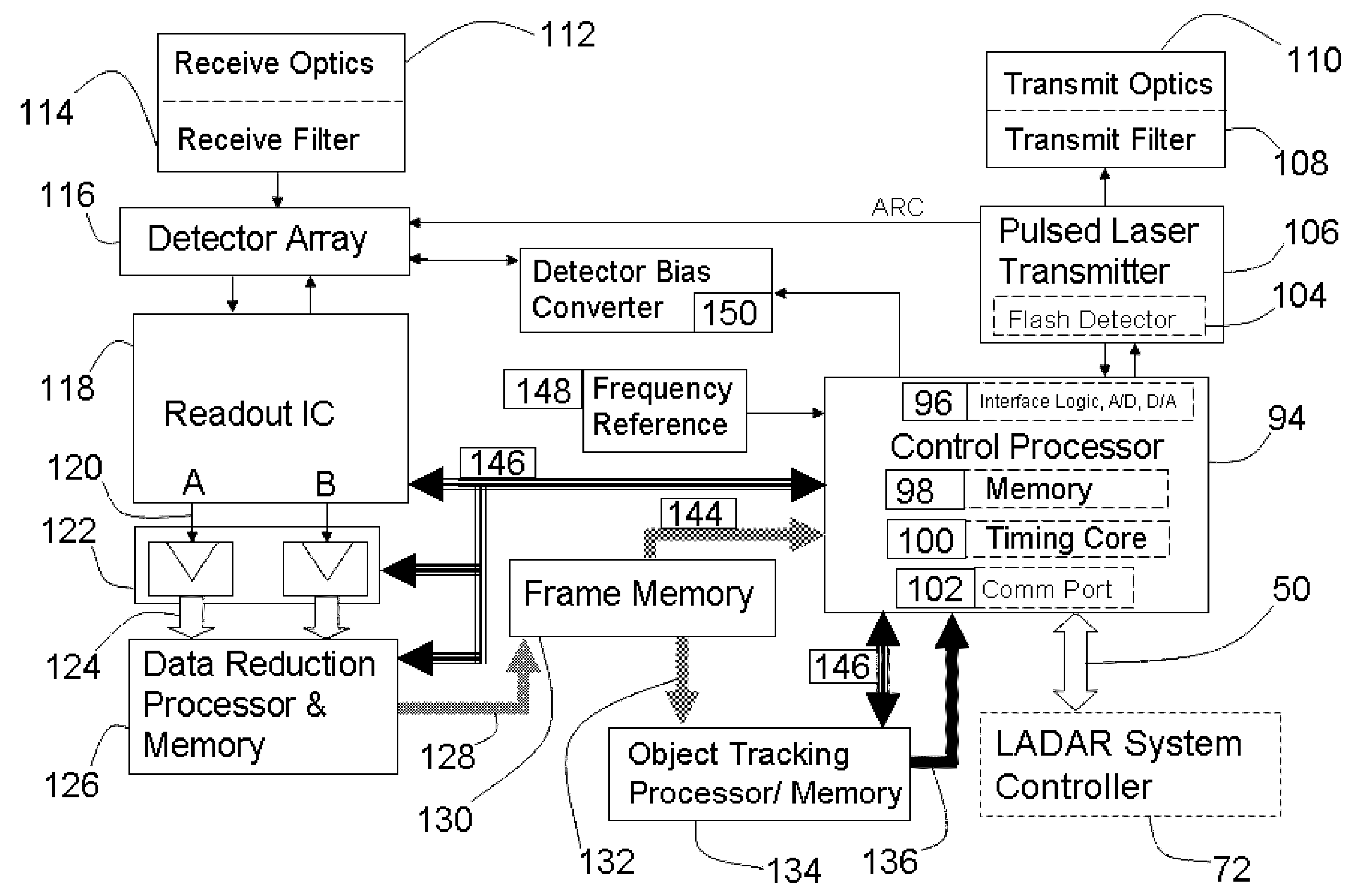
The present invention is about a ladar system that includes two ladar sensors. The first sensor has a laser transmitter that sends light to illuminate a scene, and a time zero reference circuit that signals the beginning of the laser light transmission. The sensor also has receiving optics, a receive filter, a two-dimensional array of light sensitive detectors, and a detector bias circuit. Each detector produces an electrical response signal from the reflected light. A range measuring circuit is connected to the detector output and the time zero reference output to measure the distance of the scene. The second sensor has similar components. The ladar system can also include a pulse width discriminator or a code sequence correlator to improve the accuracy of the sensor. The technical effects of this invention include improved accuracy and reliability of ladar sensors for use in various applications such as autonomous vehicles.

Problems solved by technology

Stereo systems, holographic capture systems, and those which acquire shape from motion, have not been able to demonstrate adequate performance in this application, but 3D LADAR based systems have shown the ability to rapidly capture 3-D images of objects and roadway features in the path of a moving vehicle, or travelling on an intersecting path, with sufficient speed and accuracy to allow the host vehicle to avoid collisions and road hazards, and steer the best path.
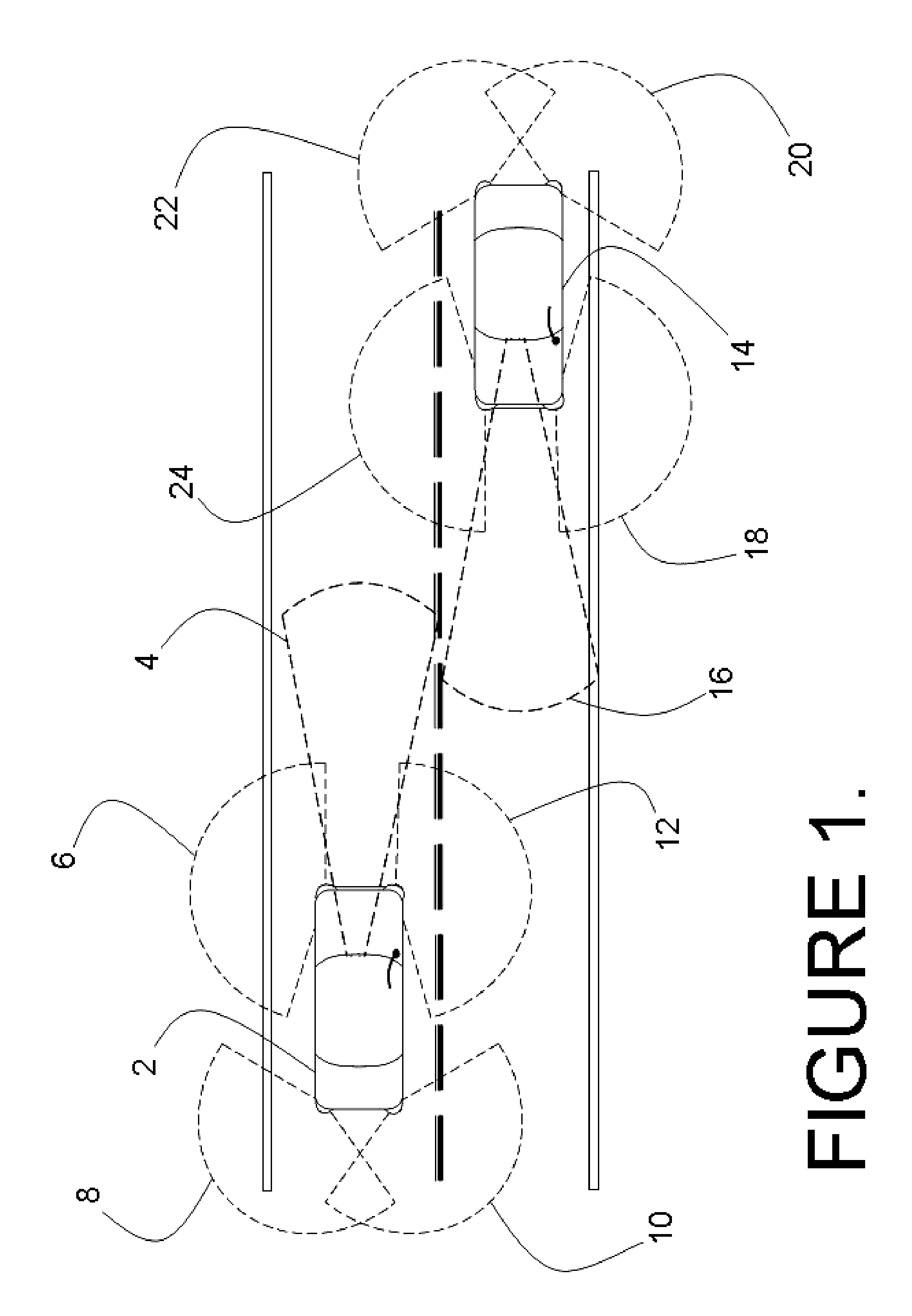
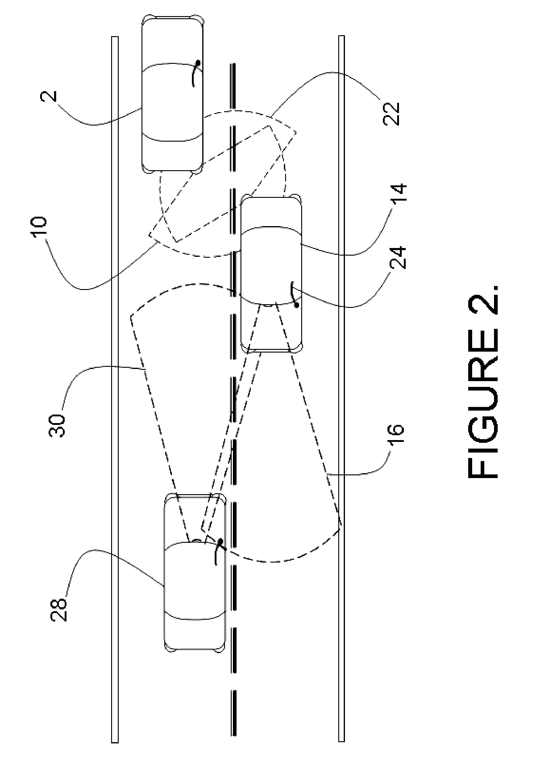
These spurious light pulses from other LADAR sensors could cause serious confusion, and false range measurements, unless means are developed to eliminate or reduce this probability.
Therefore, it is a remote, yet finite possibility there will be spurious laser pulses which have passed through the receiver optical filter and pulse width discriminator.

Method used


Image

  • LADAR sensor for a dense environment
  • LADAR sensor for a dense environment
  • LADAR sensor for a dense environment

Examples


Embodiment Construction

[0028]This application contains new subject matter related to previous U.S. Pat. Nos. 5,696,577, 6,133,989, 5,629,524, 6,414,746, 6,362,482, D463,383, and U.S. patent application Ser. No. 10 / 066,340 filed on Jan. 31, 2002 and published as US 2002 / 0117340 A1, the disclosures of which are incorporated herein by reference.

[0029]The embodiments disclosed herein enable a system for collision avoidance, object and obstacle recognition and avoidance, and ride and steering control improvements. The benefits are realized through the use of a 3-D imaging facility, comprising a vehicle mounted ladar system with an object detection and recognition capability, a steering, braking, and accelerator control system, and a ride and suspension modification system. The system includes a number of provisions which assure the independent operability of a great number of ladar sensors having overlapping fields of view. These innovations include the assignment of a multiplicity of independent wavelengths t...


PUM


Abstract

A multi-ladar sensor system is proposed for operating in dense environments where many ladar sensors are transmitting and receiving burst mode light in the same space, as may be typical of an automotive application. The system makes use of several techniques to reduce mutual interference between independently operating ladar sensors. In one embodiment, the individual ladar sensors are each assigned a wavelength of operation, and an optical receive filter for blocking the light transmitted at other wavelengths, an example of wavelength division multiplexing (WDM). Each ladar sensor, or platform, may also be assigned a pulse width selected from a list, and may use a pulse width discriminator circuit to separate pulses of interest from the clutter of other transmitters. Higher level coding, involving pulse sequences and code sequence correlation, may be implemented in a system of code division multiplexing, CDM. A digital processor optimized to execute mathematical operations is described which has a hardware implemented floating point divider, allowing for real time processing of received ladar pulses, and sequences of pulses.

Description

BACKGROUND[0001]Field of the Invention[0002]The embodiments disclosed herein relate generally to 3-D image generation and the identification and tracking of objects, and more particularly to LADAR sensors for mobile applications such as road hazard avoidance, collision avoidance, and autonomous navigation. The invention compensates for the issues arising from the operation of a multiplicity of ladar sensors operating simultaneously in a common environment allowing for a great number of LADAR sensors to be operated independently, and in close proximity.[0003]References to Related Art[0004]The 3-D imaging technology disclosed in Stettner et al, U.S. Pat. Nos. 5,446,529, 6,133,989 and 6,414,746 provides with a single pulse of light, typically pulsed laser light, all the information of a conventional 2-D picture along with the third dimensional coordinates; it furnishes the 3-D coordinates of everything in its field of view. This use is typically referred to as flash 3-D imaging in anal...

Claims


Application Information

Patent Timeline
Patent Type & Authority Patents(United States)
IPC IPC(8): G01C3/08G01S17/10G01S7/486G01S17/89G01S7/484G01S7/481G01S17/93G01S17/87G01S7/4863G01S17/894G01S17/931
CPCG01S17/89G01S7/484G01S7/486G01S7/4816G01S7/4863G01S17/10G01S17/87G01S17/936G01S17/931G01S17/894
Inventor GILLILAND, PATRICKBAILEY, HOWARDSTETTNER, ROGERKATARIA, NITIN
Owner CONTINENTAL AUTONOMOUS MOBILITY US LLC
Learn More