Method of manufacturing double reeds

a manufacturing method and double reed technology, applied in the field of woodwind instrument reeds, can solve the problems of high cost of double reeds, waste of prior art process, and high cost of good quality tools for forming double reeds, and achieve the effect of less time, easy adjustment, and tight control

Active Publication Date: 2017-03-07
RICHEY SR WILLIAM L
View PDF6 Cites 0 Cited by
  • Summary
  • Abstract
  • Description
  • Claims
  • Application Information

AI Technical Summary

Benefits of technology

[0017]The principles of the present invention provide for a new system of fabricating double reeds that take less time and which can be tightly controlled to produce useable reeds. That system is easy to adjust to work with different reed materials to produce different contoured double reeds. That system can also be readily adjusted to produce customized double reeds. It also reduces human effort and drudgery while increasing yields.

Problems solved by technology

It should be understood that good quality tools for forming double reeds are expensive, easily costing thousands of dollars.
In addition, the prior art process of making double reeds was subject to a significant amount of waste caused by human error and became tiring after making numerous double reeds.
Finished Glotin reeds have a focused, rich sound, but because it a rather soft cane reeds longevity is not particularly good.
Easy to work with, Medir finished reeds have a focused, rich sound, but are not quite as vibrant as Rigotti or Glotin.
Var select cane is a medium-hard to hard cane with a rather pale color, a dull texture and tends to be somewhat tricky to work.
Harder pieces have a much more focused sound that can be ‘bright’ whereas softer pieces are less focused and less stable.
The yield is slightly low as some tubes tend to be twisty which results in fewer finished pieces per weight.
From the foregoing it can be seen that fabricating double reeds is time consuming and the required tooling can be expensive.

Method used


Image

  • Method of manufacturing double reeds
  • Method of manufacturing double reeds
  • Method of manufacturing double reeds

Examples


Embodiment Construction

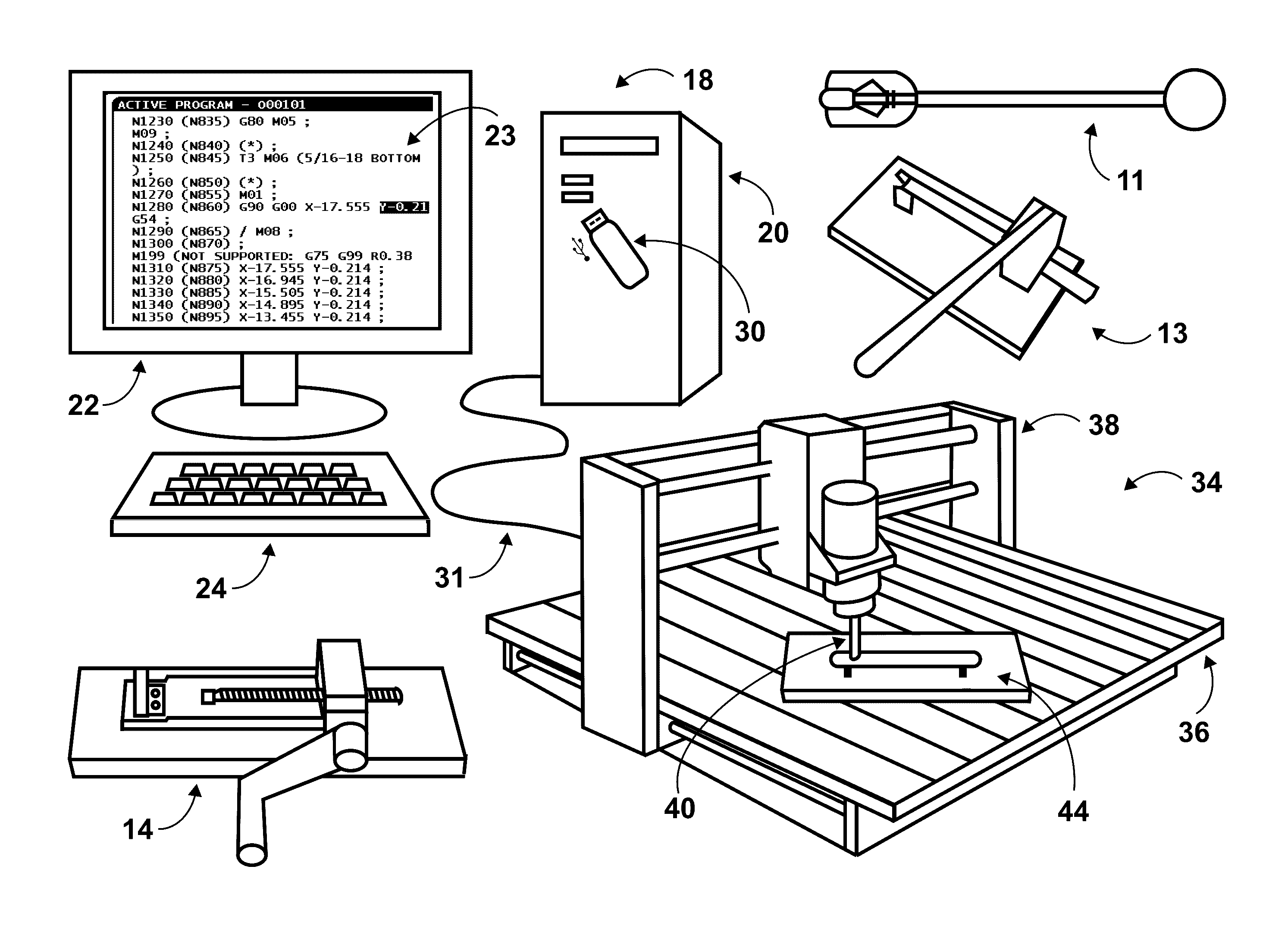
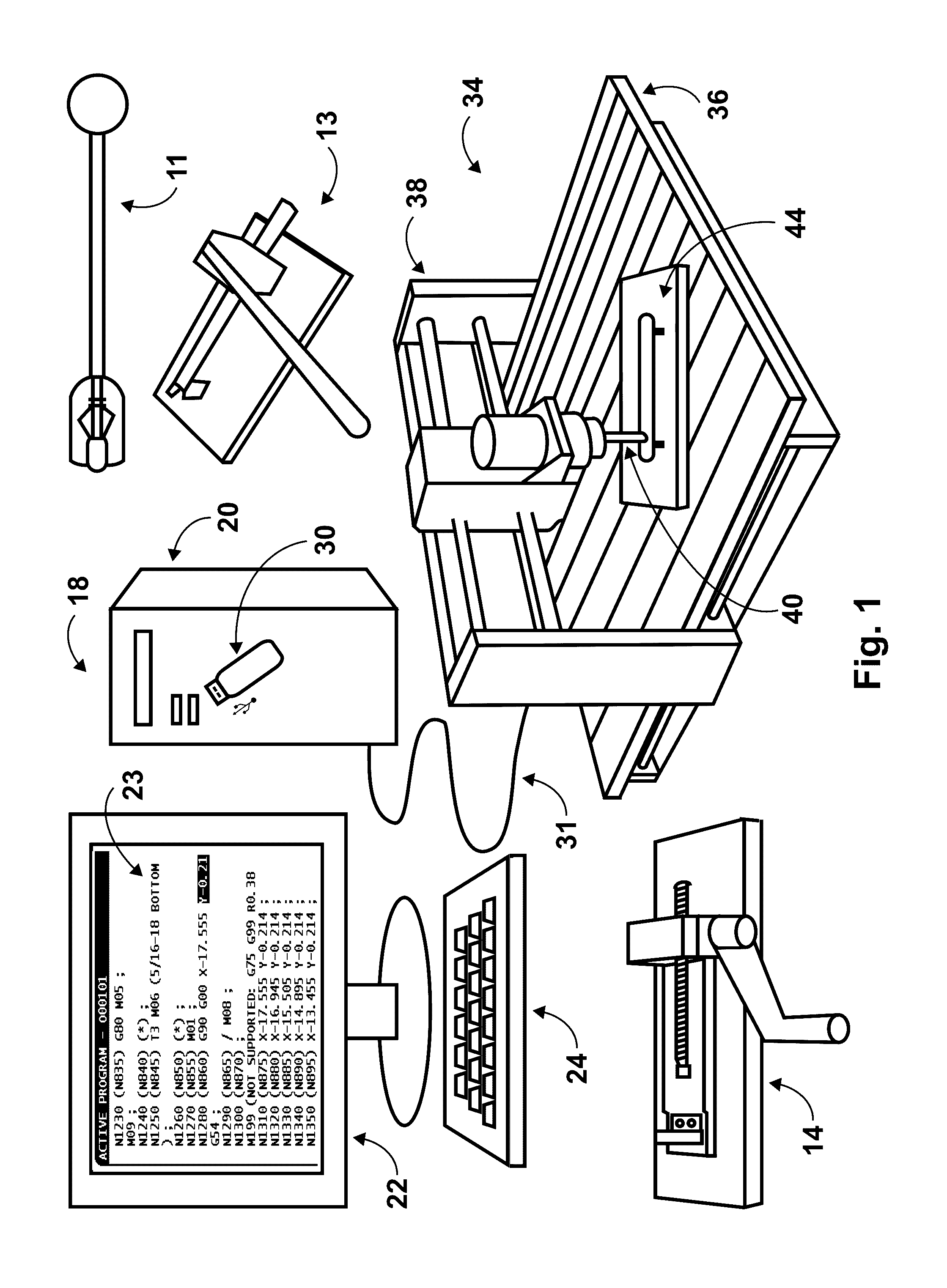
[0028]The preferred embodiment of the present invention is a reed fabrication system 10 which is depicted in FIG. 1. FIGS. 2-4 illustrate reed contours of reeds which are used in or result from the operations of the reed fabrication system 10. However, the present invention is not limited to the specifically described embodiment. A person skilled in the applicable art will appreciate that many other embodiments of the invention are possible without deviating from the basic concept of the invention. All such work-arounds fall within the scope of this invention.

[0029]In the figures like numbers refer to like elements throughout. Additionally, the terms “a” and “an” as used herein do not denote a limitation of quantity, but rather denote the presence of at least one of the referenced items. Unless otherwise specified all directional signals such as up, down, left, right and over and under are taken relative to FIG. 1.

[0030]As referred to herein, a “computer” is any processor-operated d...


PUM


Abstract

A computerized reed fabrication system having an X-Y-Z axes computer numerical controlled (CNC) machine capable of holding a tool bit. The CNC machine operates under the control of CNC software commands. The reed fabrication system further includes a tool bit held by the CNC machine and a reed holder located adjacent that tool bit. Non-transitory computer readable media stores CNC software commands. A computer reads those stored CNC software commands and sends them to the CNC machine. The CNC software commands cause the CNC machine to move the tool bit relative to the reed holder as required to fabricate a double reed from a cut piece of reed cane.

Description

FIELD OF THE INVENTION[0001]The presently disclosed subject matter is directed to woodwind instrument reeds. More particularly, the present invention relates to a novel method of manufacturing double reeds for use in woodwind instruments.BACKGROUND OF THE INVENTION[0002]Among the many different types of musical instruments are wind instruments. In general, wind instruments are musical instruments having resonators that set air into vibration when an instrument player blows air across or into a resonator. The resonator creates a pitch that depends on the configuration and dimensions of the resonator. In use the instrument player modifies the musical pitch using one or more of a wide range of playing techniques that modify the resonator or air vibration.[0003]Wind instruments are of two basic types: brass and woodwind. Some woodwind instruments use reeds to help set air in the resonators into vibrations. Of such reeded woodwind instruments there are two basic types: single reed woodwi...

Claims


Application Information

Patent Timeline
Patent Type & Authority Patents(United States)
IPC IPC(8): B27J1/00G05B19/414G10D9/02
CPCB27J1/00G05B19/4145
Inventor RICHEY, SR., WILLIAM L
Owner RICHEY SR WILLIAM L
Why Eureka
Try Eureka