Friction welding of X-ray tube components using intermediate filler materials

a filler material and x-ray tube technology, applied in the field of x-ray tubes, can solve the problems of reducing the stress applied to the base materials when joined, reducing the cycle time of the process, and reducing equipment costs, so as to reduce the required joining temperature and reduce the stress applied to the base materials. the effect of joining temperature and microstructural control

Active Publication Date: 2017-03-28
GENERAL ELECTRIC CO
View PDF2 Cites 3 Cited by
  • Summary
  • Abstract
  • Description
  • Claims
  • Application Information

AI Technical Summary

Benefits of technology

[0011]In the present invention a structure and associated process for joining dissimilar materials to form various components of an x-ray tube is illustrated that utilizes one or more intermediate or interfacial filler material members positioned between the mating or welding surfaces of the base materials to be joined. The use of the interfacial member preserves the multiple benefits of friction welding, as well as enabling the joining of dissimilar or highly dissimilar materials, decreasing the required joining temperature, and providing increased microstructural control of the resulting weld. The incorporation of the intermediate material members enables friction joining / inertial welding of highly dissimilar materials as well as significant process simplification of traditional materials systems due to the ability of the interfacial material member to interact with each of the base materials to be joined in a manner that provides a strong connection between the interfacial material member and the base materials.
[0013]The addition of an intermediate filler material into a traditional friction welded joint provides several benefits. These benefits include overall manufacturing process simplification, the expansion of the possible base materials to be joined, and the enhancement of the material structure of both the joint and the resulting structure formed by the joint and the base materials. With regard to the overall process simplification, the use of friction or inertia welding results in a lower required joining temperature, and consequently a decreased cycle time for the process, lower equipment costs, and decreased stress applied to the base materials when joined. Concerning the expansion of the dissimilar materials that may be joined, the intermediate filler material enables less expensive alloys to be used as the base materials and base materials with wider differences in material properties of the primary surface materials due the ability of the intermediate material to effectively join the various base materials. Also, with regard to the resulting structure of the materials joined using the intermediate material, the structure and performance of the joint can be tailored to provide enhanced joint properties such as the avoidance of the creation of grain growth or unwanted phases in the joint, greater joint texture control provided the greater temperature flexibility in the friction / inertia welding process, and the ability to tailor the joint to increase hermetic seal length, leading to a more torturous gas leak path, among others.

Problems solved by technology

With regard to the overall process simplification, the use of friction or inertia welding results in a lower required joining temperature, and consequently a decreased cycle time for the process, lower equipment costs, and decreased stress applied to the base materials when joined.

Method used


Image

  • Friction welding of X-ray tube components using intermediate filler materials
  • Friction welding of X-ray tube components using intermediate filler materials
  • Friction welding of X-ray tube components using intermediate filler materials

Examples


Embodiment Construction

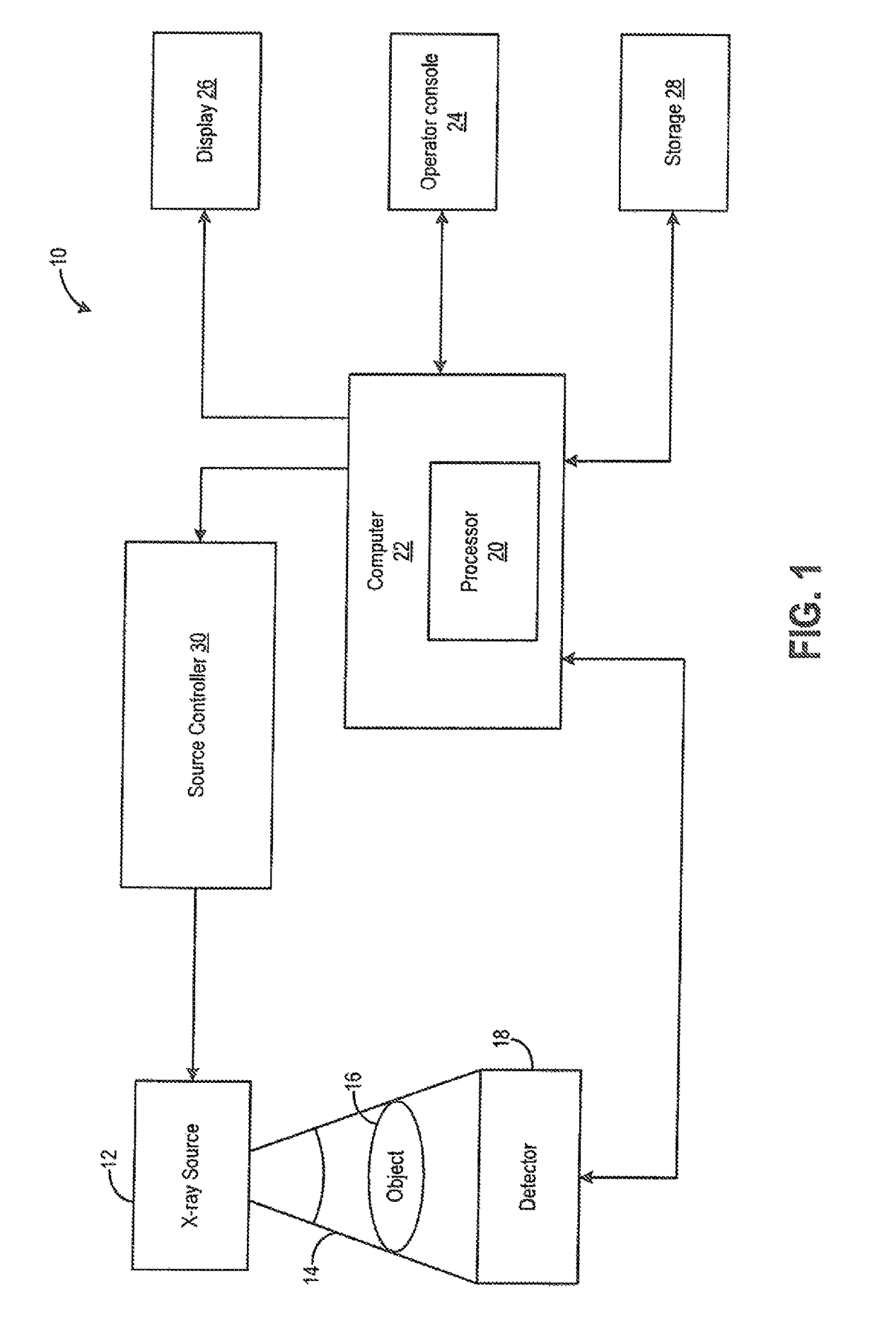
[0027]FIG. 1 is a block diagram of an embodiment of an imaging system 10 designed both to acquire original image data and to process the image data for display and / or analysis in accordance with embodiments of the invention. It will be appreciated by those skilled in the art that various embodiments of the invention are applicable to numerous medical imaging systems implementing an x-ray tube, such as x-ray or mammography systems. Other imaging systems such as computed tomography (CT) systems and digital radiography (RAD) systems, which acquire image three dimensional data for a volume, also benefit from the invention. The following discussion of x-ray system 10 is merely an example of one such implementation and is not intended to be limiting in terms of modality.

[0028]As shown in FIG. 1, imaging system 10 includes an x-ray tube or source 12 configured to project a beam of x-rays 14 through an object 16. Object 16 may include a human subject, pieces of baggage, or other objects des...


PUM

PropertyMeasurementUnit
vapor pressuresaaaaaaaaaa
temperatureaaaaaaaaaa

Abstract

A structure and associated process for joining dissimilar materials to form various components of an x-ray tube is illustrated that utilizes one or more intermediate or interfacial filler material members positioned between the primary welding or mating surfaces of the base material components to be joined. The use of the interfacial or intermediate filler material preserves the multiple benefits of friction welding, as well as enabling the joining of highly dissimilar material components, decreasing the required joining temperature, and providing increased microstructural control of the resulting weld or joint.

Description

BACKGROUND OF THE INVENTION[0001]The invention relates generally to X-ray tubes, and more particularly to structures and methods of assembly for the shaft of the anode utilized in an X-ray tube.[0002]X-ray systems may include an x-ray tube, a detector, and a support structure for the x-ray tube and the detector. In operation, an imaging table, on which an object is positioned, may be located between the x-ray tube and the detector. The x-ray tube typically emits radiation, such as x-rays, toward the object. The radiation passes through the object on the imaging table and impinges on the detector. As radiation passes through the object, internal structures of the object cause spatial variances in the radiation received at the detector. The detector then emits data received, and the system translates the radiation variances into an image, which may be used to evaluate the internal structure of the object. The object may include, but is not limited to, a patient in a medical imaging pr...

Claims


Application Information

Patent Timeline
Patent Type & Authority Patents(United States)
IPC IPC(8): H01J35/00H01J35/10B23K20/12
CPCH01J35/101B23K20/12H01J2209/18H01J2235/1006H01J35/104
Inventor POQUETTE, BEN DAVIDHEBERT, MICHAEL SCOTTROGERS, KIRK ALANSZUGYE, MICHAEL LOUISSTEINLAGE, GREGORY ALANALLEN, DONALD ROBERT
Owner GENERAL ELECTRIC CO
Why Eureka
Try Eureka