Shock damping element

a technology shock damping element, which is applied in the direction of vibration dampers, cosmonautic components, cosmonautic parts, etc., can solve the problems of limiting the use of today's solutions, and achieve the effects of enhancing the damping effect of axial forces, increasing damping efficiency, and enhancing the damping effect of shock damping elemen

Active Publication Date: 2017-04-11
RUAG SPACE
View PDF16 Cites 1 Cited by
  • Summary
  • Abstract
  • Description
  • Claims
  • Application Information

AI Technical Summary

Benefits of technology

[0007]One important advantage of the embodiment is that it allows for a possibility to tailor the stiffness in axial and lateral bending more freely. The element ensures that one kind of stiffness is not rigidly connected to the other. I.e., the element allows for the introduction of a tailored weak stiffness in the axial direction without weakening the bending stiffness by the same amount. When the shock damping element experiences a load in axial direction, i.e. tension or compression, the connection between the first and second elements at an acute angle relative the central member causes the first central member to move perpendicular to the direction of the force, i.e. to rotate along a vertical axis in a circumferential direction. When experiencing compression the first central member may move clockwise around the vertical axis and when experiencing tension the first central member may move counter-clockwise, or vice versa. The connection between the first and second elements at an acute angle relative the central member also causes the shock damping element to be able to have a greater bending stiffness than axial stiffness. This is caused by that the first and second elements directs the compressive or tension force to be directed to the first central member which will move perpendicularly to the direction of the applied force. A bending load experienced by the shock damping element causes one part of the shock damping element to experience compression and a part on the opposite side of the shock damping element to experience tension. This means that the part of the first shock damping element being compressed strives to rotate the first central member in a first direction around its vertical axis, while at the same time the part of the first shock damping element being tensioned strives to rotate the first central member in a second direction, opposite the first direction. The opposite movement of the two parts of the first central member essentially hinders movement of the first central member leading to that the bending stiffness is largely maintained.
[0029]One advantage with the embodiments is that it is possible to tailor, i.e. adapt the axial stiffness of the shock damping element while essentially maintaining the bending stiffness. The relationship between the bending stiffness and the axial stiffness can be varied by varying the characteristics of one or more of the parts of the shock damping element as mentioned above.

Problems solved by technology

This limits the use of today's solutions.

Method used


Image

  • Shock damping element
  • Shock damping element
  • Shock damping element

Examples


Embodiment Construction

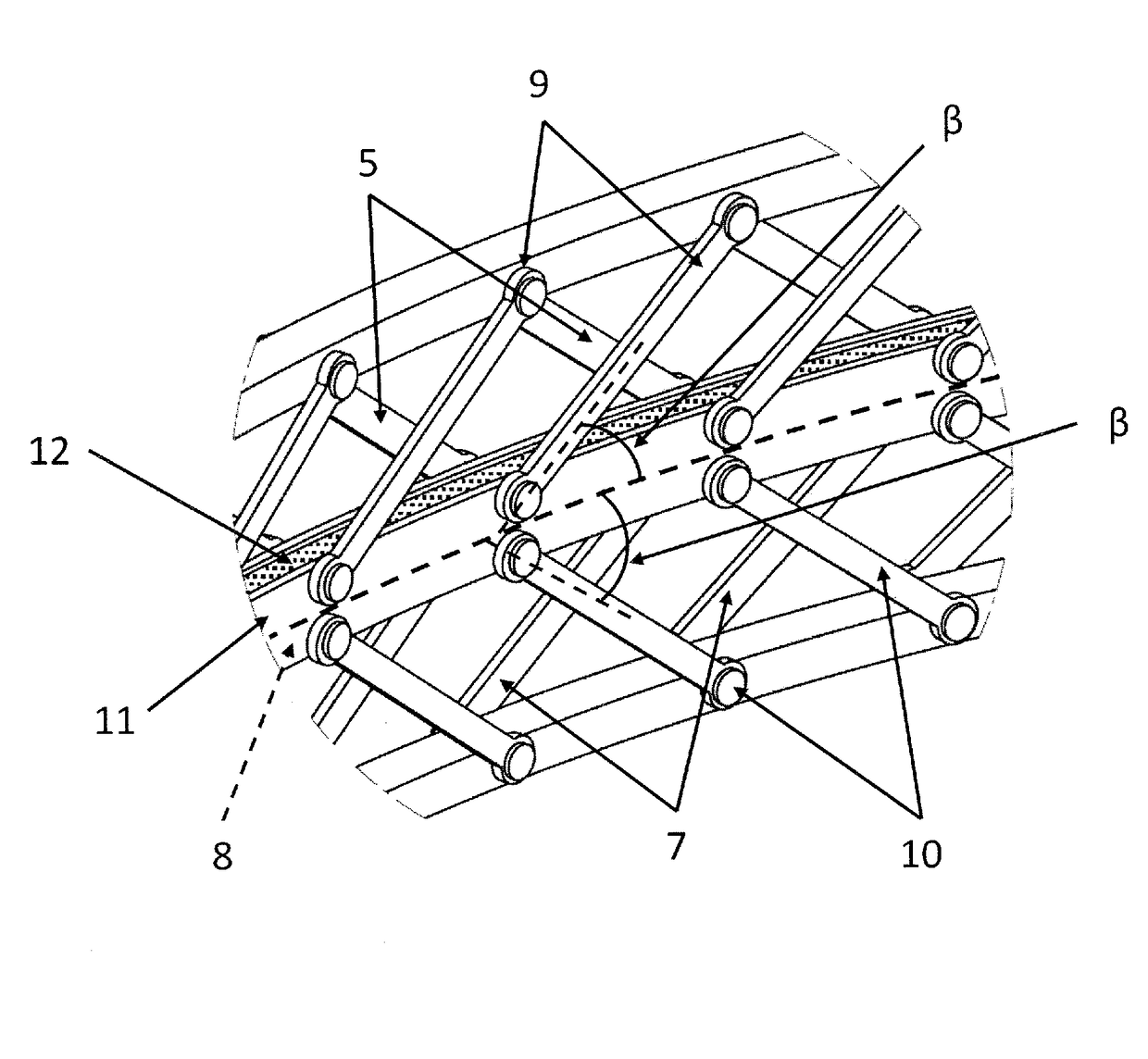
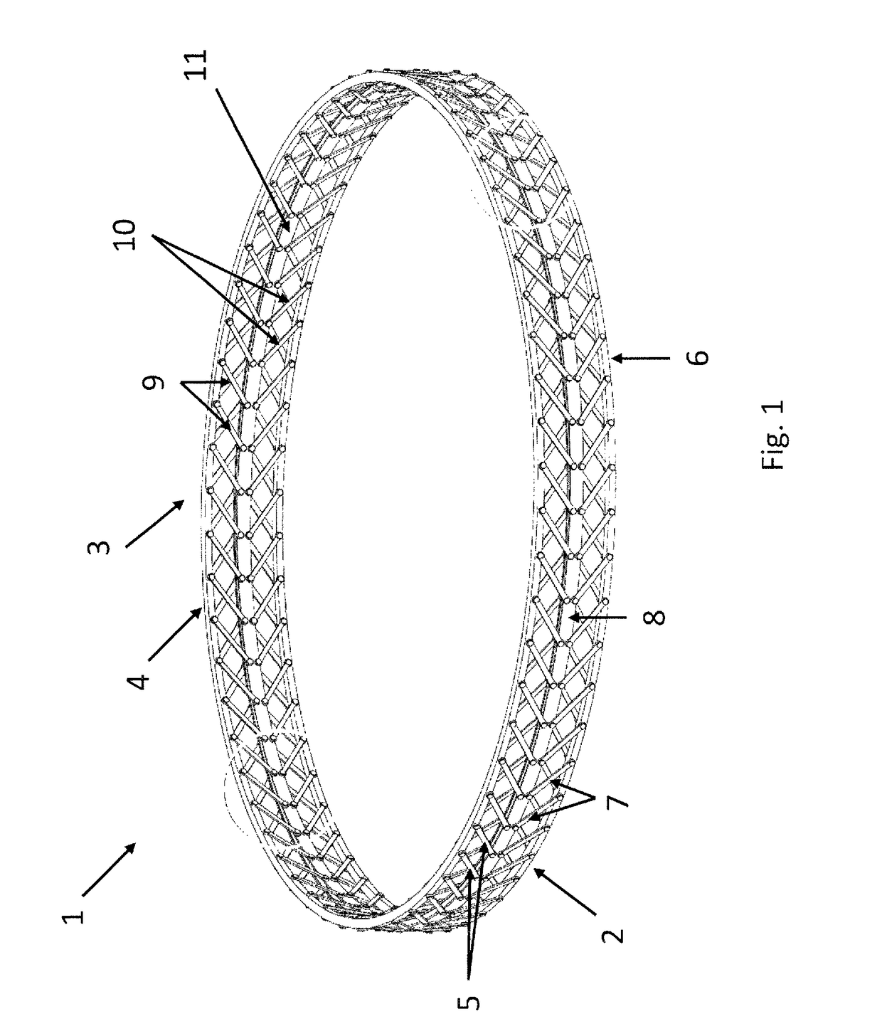
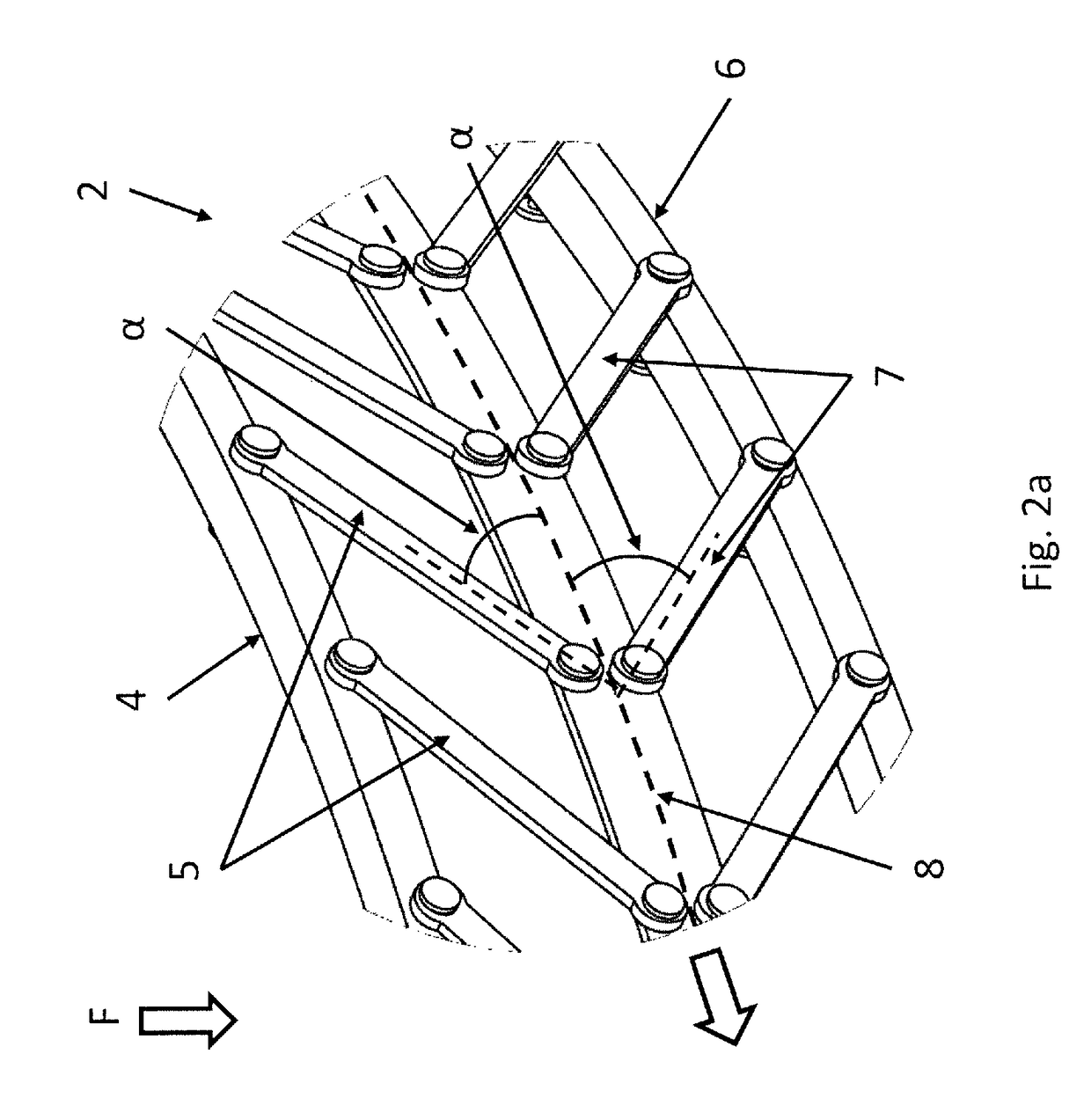
[0038]FIG. 1 schematically shows a first example of a shock damping element 1. In the first example, the shock damping element 1 comprises a first shock damping structure 2 and a second shock damping structure 3. The first shock damping structure 2 comprises a first circumferential support member 4 and a multitude of first elements 5. The first shock damping structure 2 further comprises a second circumferential support member 6 and a multitude of second elements 7. The first elements 5 and the second elements 7 are located at opposite sides of a first central member 8, e.g. above and below in a vertical direction. The first elements 5 in this example comprises links being rotatably connected at a first end to the first circumferential support member 4 and at a second end to the first central member 8. The second elements 7 in this example comprise links being rotatably connected at a first end to the second circumferential support member 6 and rotatably connected at a second end to...


PUM


Abstract

A shock damping element includes a first shock damping structure that includes a multitude of first elements, a multitude of second elements and a first central member. The first elements and the second elements are located at opposite sides of the first central member. The first and second elements extend towards the first central member at a first acute angle (α) relative the first central member and are connected to the first central member. The first and second elements extend in a first direction circumferentially.

Description

RELATED APPLICATIONS[0001]This application claims priority to European Application No. 14182431.8, filed Aug. 27, 2014, the contents of which is incorporated herein by reference in its entirety.TECHNICAL FIELD[0002]The embodiments below relate to a shock damping element having a closed cross section.BACKGROUND ART[0003]Shock damping structures used in for instance the building of structures which experience both axial and bending vibrations are known in the art. The shock damping structures can be used as interface rings or adapters between a launch vehicle and a payload such as a satellite. These structures experience both axial and bending vibrations and require some kind of damping arrangement in order to absorb vibrations and shocks. Today's damping arrangements all rely on a combination of introducing a weak stiffness, for instance in the form of spring element combined with an energy absorbing material. Today's damping arrangements lower the axial stiffness by the same amount ...

Claims


Application Information

Patent Timeline
Patent Type & Authority Patents(United States)
IPC IPC(8): F16F7/00F16F1/02B64G1/22F16F15/02
CPCF16F7/00B64G1/22F16F1/028F16F15/02
Inventor THUSWALDNER, MICHAELHELMERSSON, ANDERSARULF, ORJAN
Owner RUAG SPACE
Why Eureka
Try Eureka