
Monolithic ceramic electronic component and method for manufacturing the same

a technology of ceramic electronic components and monolithic ceramics, applied in the direction of fixed capacitor details, stacked capacitors, fixed capacitors, etc., can solve the problems of increased product cost, degraded reliability, and high price of electric conductive paste containing metal resinate, and achieve excellent plating liquid resistance, high reliability, and suppressed or prevented penetration of plating liquid into the inner part

Active Publication Date: 2017-04-11
MURATA MFG CO LTD
View PDF16 Cites 2 Cited by
  • Summary
  • Abstract
  • Description
  • Claims
  • Application Information

AI Technical Summary

Benefits of technology

The present invention is a method for manufacturing a highly reliable monolithic ceramic electronic component that prevents reduction in strength and degradation of reliability. The method includes the formation of outer electrodes with an inorganic substance containing at least Si, and the formation of a crystal phase containing at least Si, Ti, and Ba at the interfaces to the ceramic layer in the peripheral end portions of the outer electrodes. This results in the interface forming a barrier for the plating liquid, preventing its penetration into the inner part of the component. This method suppresses elution of ceramic constituents from the ceramic layer and reduces the possibility of causing reduction in strength and degradation of reliability in the monolithic ceramic element. As a result, a highly reliable monolithic ceramic electronic component can be obtained.

Problems solved by technology

However, in general, the electrically conductive paste containing the metal resinate is expensive and there are problems that, for example, an increase in product cost is caused.
As a result, there is a problem that the reliability is degraded because the strength of the monolithic ceramic element 133 in the vicinity of the going-around front end portions 144a and 144b of the outer electrodes 135a and 135b is reduced, a crack occurs during reflow, and bending strength becomes insufficient.

Method used


Image

  • Monolithic ceramic electronic component and method for manufacturing the same
  • Monolithic ceramic electronic component and method for manufacturing the same
  • Monolithic ceramic electronic component and method for manufacturing the same

Examples


Embodiment Construction

[0031]The features of the present invention will be described below in further detail with reference to the embodiments according to the present invention.

[0032][Monolithic Ceramic Capacitor]

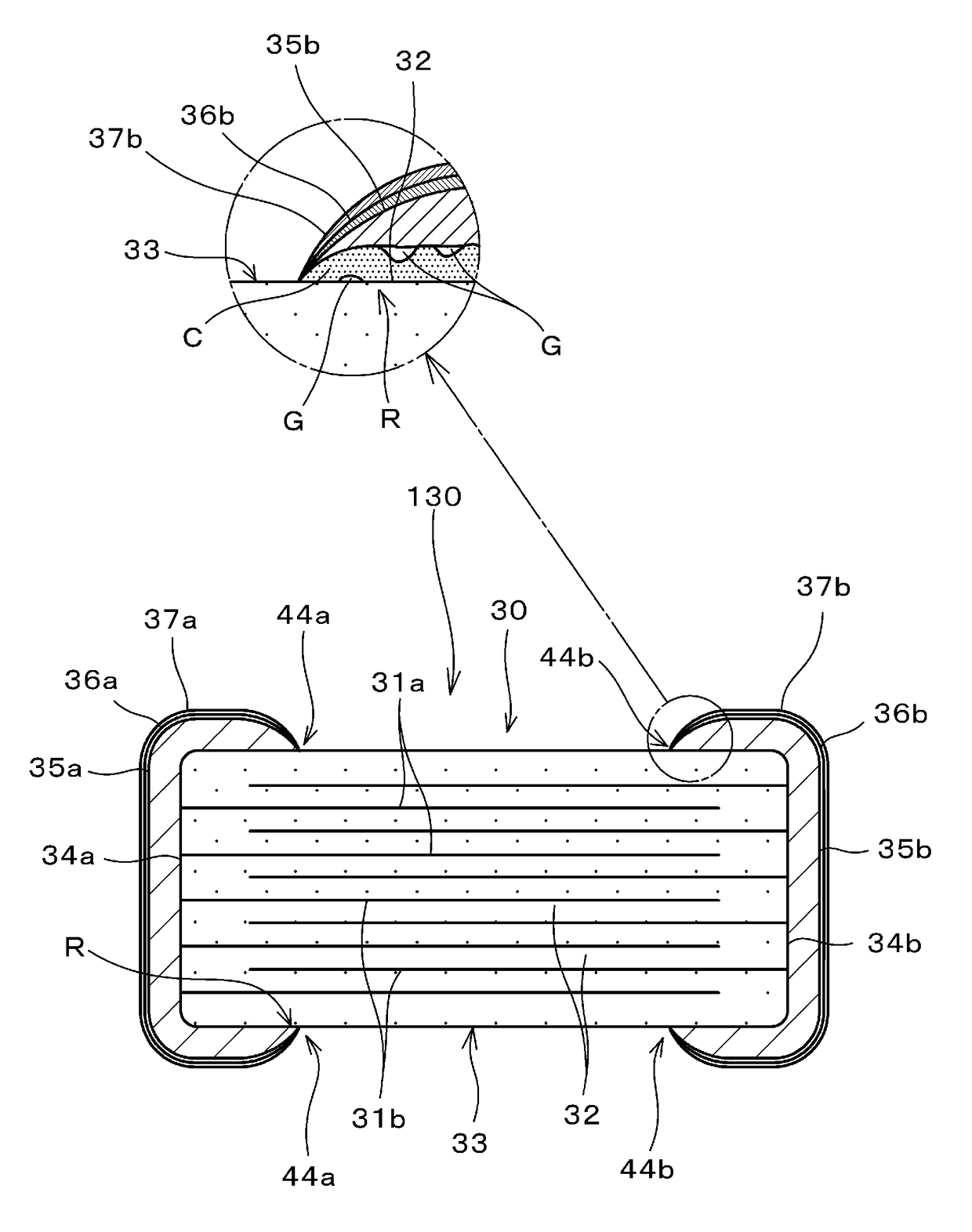
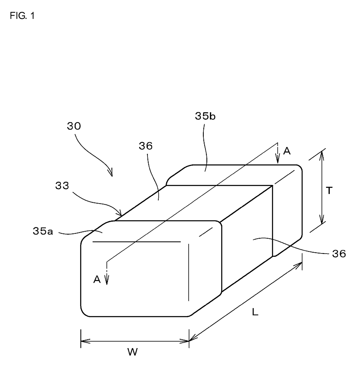
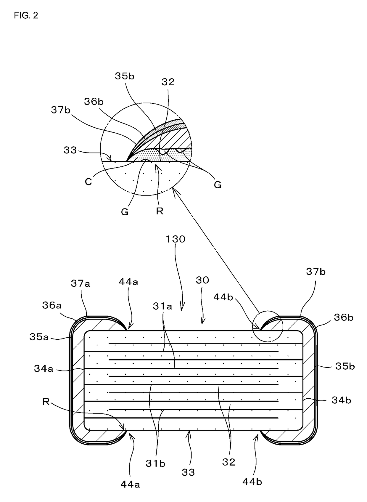
[0033]FIG. 1 is a perspective view showing a monolithic ceramic electronic component (here, monolithic ceramic capacitor) according to an embodiment of the present invention. FIG. 2 is a sectional view of a cross-section taken along a line A-A shown in FIG. 1.

[0034]As shown in FIGS. 1 and 2, a monolithic ceramic capacitor 30 includes a sintered monolithic ceramic element 33 (ceramic capacitor element) in which a plurality of inner electrodes 31a and 31b are stacked with ceramic layers 32 therebetween.

[0035]Meanwhile, one end of the inner electrodes 31a and 31b are led to respective end surfaces 34a and 34b of the monolithic ceramic element 33.

[0036]Then, a pair of outer electrodes 35a and 35b are disposed on both end surfaces of 34a and 34b of the monolithic ceramic element 33 in such a way as t...


PUM

PropertyMeasurementUnit
temperatureaaaaaaaaaa
oxygen electromotive forceaaaaaaaaaa
temperatureaaaaaaaaaa

Abstract

A monolithic ceramic electronic component having outer electrodes that include an inorganic substance containing at least Si, a crystal phase C containing at least Si, Ti, and Ba at the interfaces to a ceramic layer in peripheral end portions of the outer electrodes. A value of the crystal phase area ratio indicating the relationship between the area of the crystal phase C and the area of a glass phase G, which are formed at the interface to the ceramic layer, in a region within 5 μm from the peripheral end portion of the outer electrode is within a range of 75% to 98%.

Description

CROSS REFERENCE TO RELATED APPLICATIONS[0001]The present application is a continuation of International application No. PCT / JP2013 / 074061, filed Sep. 6, 2013, which claims priority to Japanese Patent Application No. 2012-224220, filed Oct. 9, 2012, the entire contents of each of which are incorporated herein by reference.FIELD OF THE INVENTION[0002]The present invention relates to a monolithic ceramic electronic component, for example, a monolithic ceramic capacitor, and a method for manufacturing the same. In particular, the present invention relates to a monolithic ceramic electronic component including outer electrodes disposed on the surface of a monolithic ceramic element, which includes inner electrodes, in such a way as to be connected to the above-described inner electrodes and a method for manufacturing the monolithic ceramic electronic component.BACKGROUND OF THE INVENTION[0003]For example, a monolithic ceramic capacitor, which is one of representatives of monolithic ceram...

Claims


Application Information

Patent Timeline
Patent Type & Authority Patents(United States)
IPC IPC(8): H01G4/228H01G4/12H01G4/30H01G4/012H01G4/232H01G4/248H01G4/008H01G4/00
CPCH01G4/30H01G4/008H01G4/0085H01G4/012H01G4/1209H01G4/1227H01G4/2325H01G4/248
Inventor OMORI, TAKASHIKOGA, SEIJIIKEDA, JUN
Owner MURATA MFG CO LTD
Learn More