
Power converter output stage using heat dissipating bus bars

Active Publication Date: 2017-05-02
BEL POWER SOLUTIONS INC
View PDF8 Cites 11 Cited by
  • Summary
  • Abstract
  • Description
  • Claims
  • Application Information

AI Technical Summary

Benefits of technology

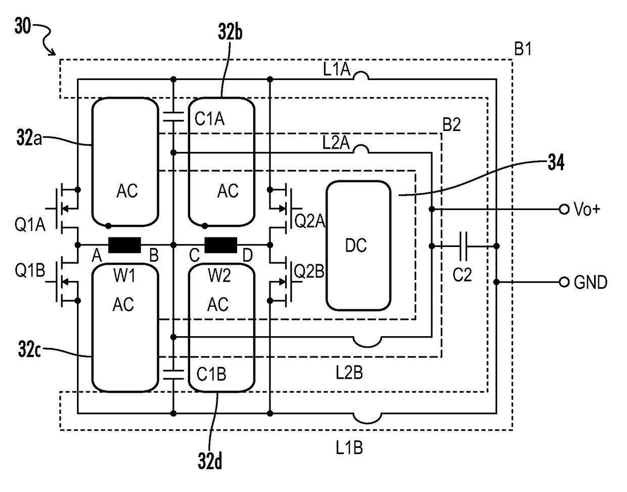
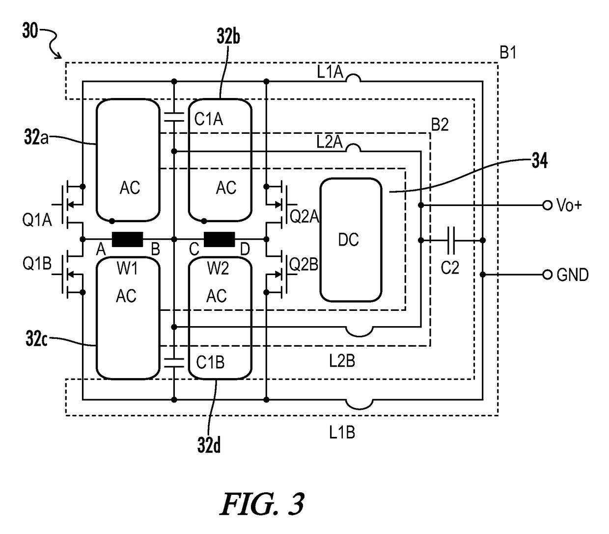
The present invention describes a new way to create a high-output DC / DC converter that is small and efficient. It uses a combination of printed circuit boards, transformers, synchronous rectifiers, and bus bars. This design also provides noise filtering and effective cooling, ensuring the devices are always working optimally. Additionally, a third capacitor and a magnetic element can be added to smooth the output voltage and increase the filtering inductance of the second bus bar. Overall, this invention presents a way to achieve a dense, efficient, and cooling-effective output stage for a DC / DC converter.

Problems solved by technology

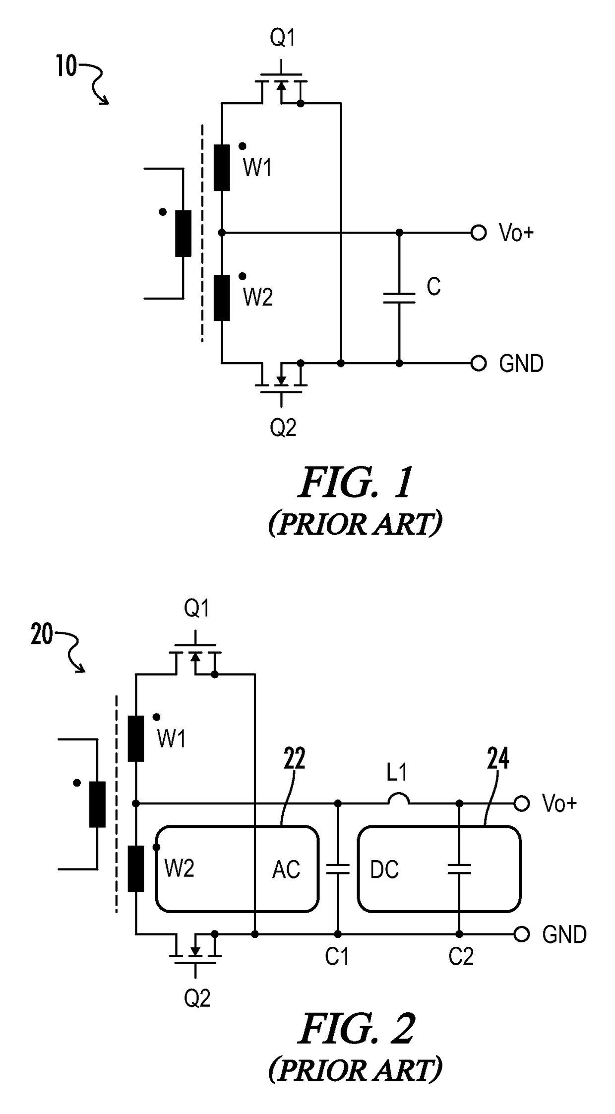
In such cases, the transformer and the MOS switches cannot be placed in close proximity to each other.
This results in parasitic inductance, further causing ringing and hence overshoot of the voltage across the switches, which again requires an oversizing of the switches.
Further, the physical separation of the transformer and the synchronous rectifiers result in significant conduction losses in the wiring.
With this type of package for the synchronous rectifiers, it is typically impractical or even impossible to increase the overall power density of the converter because of the size of the components.
Further, the associated parasitic characteristics substantially prohibit an increase in the switching frequency.

Method used


Image

  • Power converter output stage using heat dissipating bus bars
  • Power converter output stage using heat dissipating bus bars
  • Power converter output stage using heat dissipating bus bars

Examples


Embodiment Construction

[0024]Where the various figures may describe embodiments sharing various common elements and features with other embodiments, similar elements and features are given the same reference numerals and redundant description thereof may be omitted below.

[0025]In various embodiments, a switched mode power supply as described herein may typically be implemented for or otherwise incorporated within a power shelf or an equivalent rack-mount structure by which DC power may be provided to, for example, power servers, storage or networking equipment. An exemplary power shelf may typically include or otherwise be placed in proximity to a cooling fan network to generate a forced cooling airstream across the power supply, for example drawing or pushing cool air through the system to replace or otherwise transfer heated air from the electrical components.

[0026]Various embodiments of the power supply may include an input power source, an input power stage further including a power conversion circuit...


PUM


Abstract

A dense and efficient output stage for a DC / DC converter includes center tapped secondary windings of a transformer having an offset core with respect to a PCB, two pairs of synchronous rectifiers configured to define two pairs of paralleled symmetrical AC loops respective to the secondary windings, and at least two bus bars disposed within a forced cooling airstream to act as heat sinks for the synchronous rectifiers, while further providing a filtering impedance between the transformer windings and an output capacitance. A split capacitance is disposed in close proximity with the synchronous rectifiers to filter out ripple current, in one embodiment characterized by first and second capacitors each respectively coupled between opposing ends of the first and second bus bars, wherein the bus bars are arranged about at least three sides of the transformer core.

Description

CROSS-REFERENCES TO RELATED APPLICATIONS[0001]This application claims benefit of U.S. Provisional Patent Application No. 61 / 943,065, filed Feb. 21, 2014, and which is hereby incorporated by reference.[0002]A portion of the disclosure of this patent document contains material that is subject to copyright protection. The copyright owner has no objection to the reproduction of the patent document or the patent disclosure, as it appears in the U.S. Patent and Trademark Office patent file or records, but otherwise reserves all copyright rights whatsoever.BACKGROUND OF THE INVENTION[0003]The present invention relates generally to DC / DC power converters. More particularly, the present invention pertains to the use and configuration of bus bars in an output stage of a DC / DC power converter.[0004]Conventional DC / DC switch mode power converters use synchronous rectification on the output of the transformer isolating the primary and secondary circuits. The synchronous rectifiers are often impl...

Claims


Application Information

Patent Timeline
IPC IPC(8): H02M7/217
CPCH02M7/217H02M3/28H02M3/33592H02M7/003Y02B70/10
Inventor WILD, URSFENO, IVAN
Owner BEL POWER SOLUTIONS INC
Learn More