Voltage-tunable optical filters for instrumentation applications

a technology of voltage-tunable optical filters and instrumentation, applied in the field of optical filters, can solve the problems of limiting the useful applications of mechanical configurations, limiting the signal loss, and relatively slow and bulky, and achieve the effect of simplifying the ability of users

Active Publication Date: 2017-05-09
II VI DELAWARE INC
View PDF22 Cites 19 Cited by
  • Summary
  • Abstract
  • Description
  • Claims
  • Application Information

AI Technical Summary

Benefits of technology

[0007]In accordance with one embodiment of the present invention, a series combination of a shortwave pass (SWP) filter and a longwave pass (LWP) filter is provided in an arrangement where the filters are separately and independently controlled by voltages applied to the respective filters. The applied voltages modify the response profile of the associated filters, where changes in a given applied voltage change the response for the associated filter. The ability to independently tune both the SWP and LWP filters allows for the combined result of their series combination to modify both the center wavelength (CWL) and bandwidth (BW) of the overall filter resulting from their combination.
[0008]In one embodiment, the inventive voltage-tunable filter is utilized as the excitation filter in a fluorescence spectroscopy system. In this embodiment, the voltages applied to the SWP and LWP filters can be controlled to provide a relatively narrow bandwidth filter response, with a CWL that is tunable over a wide spectral range (for example, over three octaves in the IR regime, e.g., tunable from 8 μm to 32 μm). This capability to change the CWL of the excitation filter simplifies the ability of the user to change the specific dye being evaluated (or optimize the measurement capabilities with the existing dye), as well as provide for the utilization of hyperspectral excitation, without the need to physically change the filter components (e.g., by using a “filter wheel”), as required by the prior art.

Problems solved by technology

Problems with signal loss remain.
As such, limitations associated with, for example, movable parts, angular displacement between elements and the like result in relatively slow response times (with respect to initiating the mechanical action to implement wavelength tuning), limiting the useful applications of these mechanical configurations.
Tunable filters based on acousto-optic configurations have also been developed, but are known to also be relatively slow and bulky and, moreover, are typically limited in the wavelength range across which the tuning may be performed.

Method used


Image

  • Voltage-tunable optical filters for instrumentation applications
  • Voltage-tunable optical filters for instrumentation applications
  • Voltage-tunable optical filters for instrumentation applications

Examples


Embodiment Construction

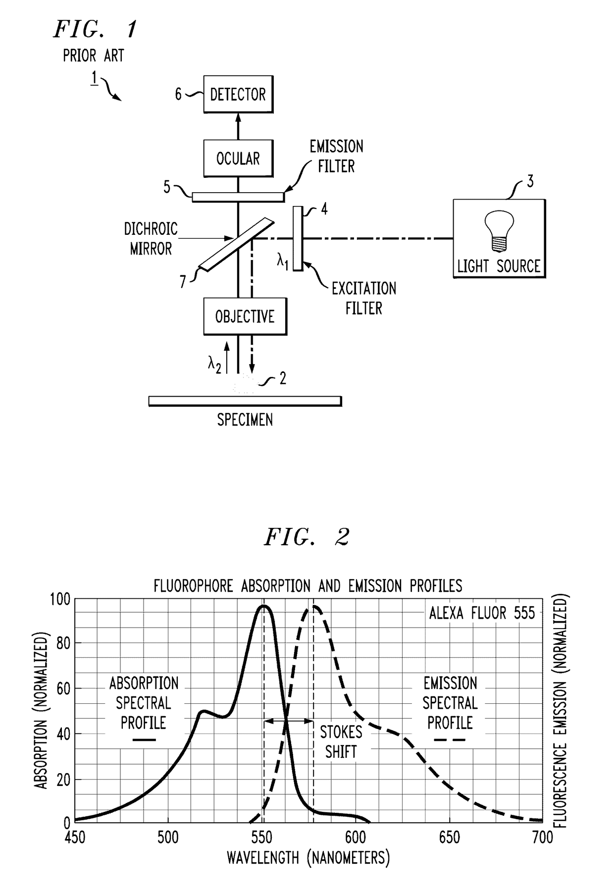
[0053]As will be discussed in detail below, there are a variety of different applications for a tunable optical filter in fluorescence-based imaging systems. FIG. 1 illustrates an exemplary prior art epifluorescence microscope 1 that benefits from the utilization of the inventive voltage-controlled tunable optical filter. Fluorescence microscopy provides magnified images of tissues, cells or other components of a specimen, using light emission for a plurality of fluorescent dyes that can be attached to specific components or features of the specimen. Referring to FIG. 1, a specimen 2 is prepared using one or more known fluorescent dyes (such as DAPI, GFP, RFP, YFP, an Alexa dye, Cy2, Cy3, Atto 488, fluorescein, etc.). A broadband light source 3 is used to illuminate specimen 2. As shown, the broadband output from light source 3 is first passed through an excitation filter 4 that is configured to pass only the specific wavelength range (denoted λ1) that interacts with the specific dy...


PUM

PropertyMeasurementUnit
conductiveaaaaaaaaaa
transparentaaaaaaaaaa
cut-off wavelength λSaaaaaaaaaa

Abstract

A series combination of a shortwave pass (SWP) filter and a longwave pass (LWP) filter is provided in an arrangement where the filters are separately and independently controlled by voltages applied to the respective filters. The applied voltages modify the response profile of the associated filters, where changes in the voltage applied to the SWP filter changes its cut-off wavelength λS and changes in the voltage applied to the LWP filter changes its cut-on wavelength λL (the bandwidth of the combined arrangement between the span between λL and λS). The ability to independently tune both the SWP and LWP filters allows for the combined result of their series combination to modify both the center wavelength (CWL) and bandwidth (BW) of the overall filter resulting from their combination.

Description

TECHNICAL FIELD[0001]The present invention relates to optical filters used in instrumentation applications and, more particularly, to a voltage-tunable optical filter that is variable in both center wavelength and bandwidth, and able to provide real-time changes to filter responses for various instrumentation applications (e.g., fluorescence spectrometry, Raman spectrometry, flow cytometry, etc.).BACKGROUND OF THE INVENTION[0002]Fluorescence microscopy typically involves the use of three separate optical filters: an excitation filter used to select an appropriate wavelength from the system illumination source, an emission filter to limit the fluorescence wavelength spectrum received at a detector from an illuminated specimen, and a dichroic filter positioned between both the excitation filter and the specimen, as well as the specimen and emission filter. The dichroic filter is used to separate the excitation wavelength band from the emission wavelength band. Raman spectroscopy uses ...

Claims


Application Information

Patent Timeline
Patent Type & Authority Patents(United States)
IPC IPC(8): G01N21/64G01J3/44G01J3/12G02B21/00G02B5/00G02B21/16G02B21/06G02B5/20
CPCG02B5/204G02B21/16G02B21/06G01J3/44G01J3/12G02B21/0064G02B5/008G02B5/207G01J2003/1213G02F1/0121G01J3/0237B82Y20/00G01J3/4406G01J2003/1282G02F2203/055G02F2203/10G01N21/6458G01N21/65G01N15/1434G01N2015/1006G01N15/1459
Inventor SOMMER, THOMAS RADFORDKASTANIS, WILLIAM
Owner II VI DELAWARE INC
Why Eureka
Try Eureka