Battery, battery pack, electronic apparatus, electrically driven vehicle, electrical storage device, and power system

a battery pack and electronic device technology, applied in battery overvoltage protection, secondary cell manufacture, safety/protection circuits, etc., can solve the problem of local overvoltage on the electrode surface that tends to increase during charging and discharging, and the cycle lifespan is apt to decrease, so as to achieve the effect of suppressing capacity deterioration

Active Publication Date: 2017-05-09
MURATA MFG CO LTD
View PDF36 Cites 5 Cited by
  • Summary
  • Abstract
  • Description
  • Claims
  • Application Information

AI Technical Summary

Benefits of technology

[0014]According to the present disclosure, it is possible to suppress deterioration in capacity due to repetition of charging and discharging of a battery.
[0015]Additional features and advantages are described herein, and will be apparent from the following Detailed Description and the figures.BRIEF DESCRIPTION OF THE FIGURES
[0016]FIG. 1 is an exploded perspective view illustrating a configuration of a laminate film type nonaqueous electrolyte battery according to a first embodiment of the present disclosure.
[0017]FIG. 2 is a cross-sectional view illustrating a cross-sectional configuration along line I-I in a wound electrode body illustrated in FIG. 1.
[0018]FIG. 3A is a schematic cross-sectional view illustrating a configuration example of a first separator of the present disclosure. FIG. 3B is a schematic cross-sectional view illustrating a configuration example of a second separator of the present disclosure.
[0019]FIG. 4 is an exploded perspective view illustrating a configuration example of a simple battery pack.

Problems solved by technology

In addition, in this case, when using a separator outside of the range in the present disclosure, it is difficult to mitigate an over-voltage that is caused by a current density that increases due to the area density of the positive electrode active material layer, and thus the cycle lifespan is apt to decrease due to a decomposition reaction of an electrolyte solution.
However, in the case of applying the technology disclosed in PTL 2 to a separator having a large film thickness, ion permeability of the separator decreases, and thus a local over-voltage on an electrode surface tends to increase during charging and discharging.
Particularly, in a case where the area density of an electrode increases beyond an arbitrary range, clogging of the separator occurs due to electrolyte solution decomposition due to the over-voltage, and as a result, the cycle characteristics deteriorate.
In addition, when exceeding 150 μm, processing is significantly difficult, and the thickness of a laminate film 52 increases, and thus a volume efficiency of the nonaqueous electrolyte battery tends to decrease.
On the other hand, for example, in a case of using a nickel-based positive electrode active material such as LiNiO2, thermal stability in a charging state, which decreases at a final stage of a discharging curve (a flat region is short), is not good (stability of a battery is relatively not good), the cut-off voltage is low, and a large amount of gas occurs during high-temperature storage.
As a result, an effect of a decrease in capacity tends to further increase.

Method used


Image

  • Battery, battery pack, electronic apparatus, electrically driven vehicle, electrical storage device, and power system
  • Battery, battery pack, electronic apparatus, electrically driven vehicle, electrical storage device, and power system
  • Battery, battery pack, electronic apparatus, electrically driven vehicle, electrical storage device, and power system

Examples


first embodiment

1. First Embodiment

Configuration of Battery

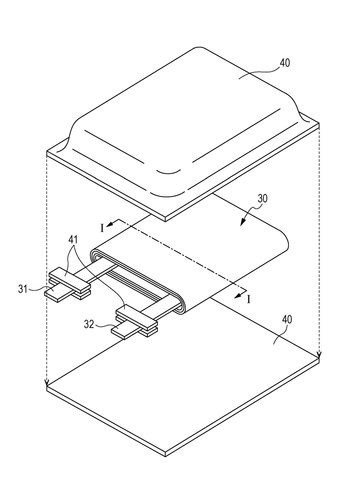
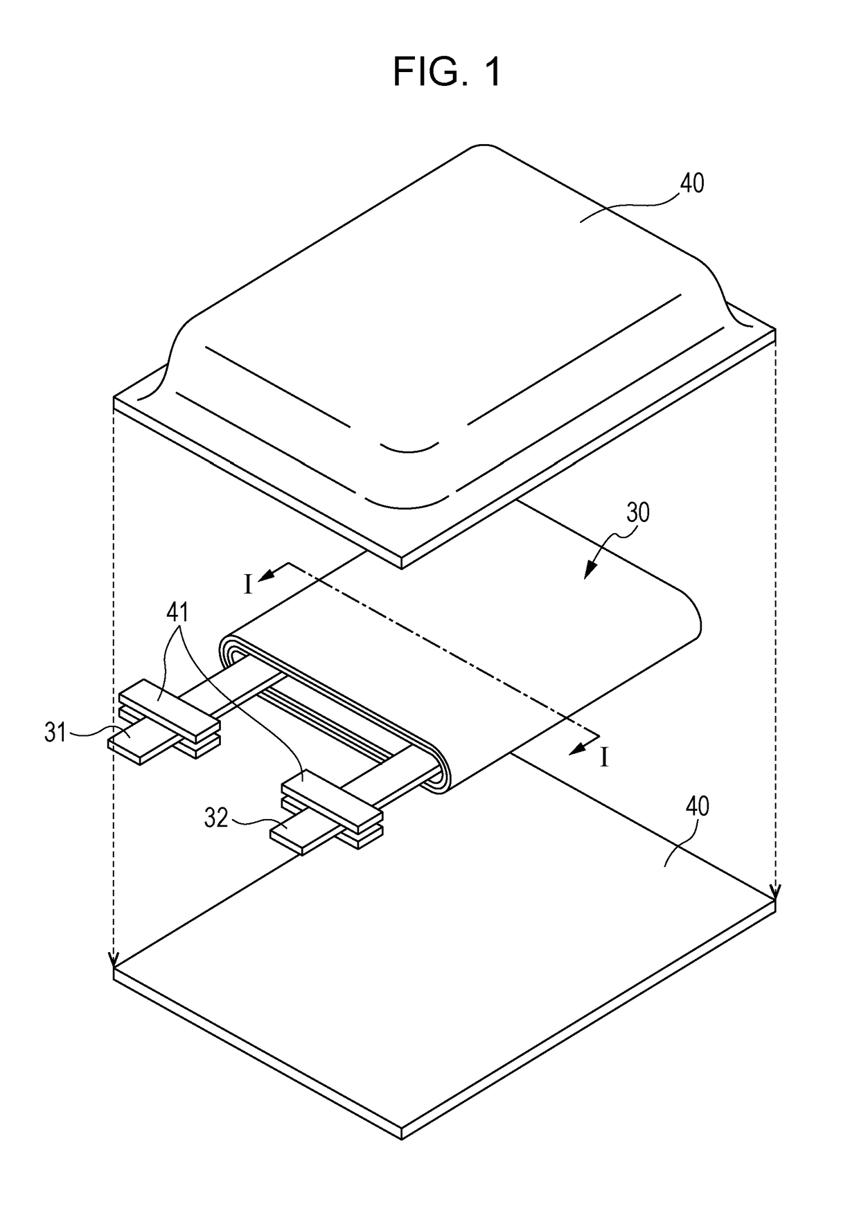
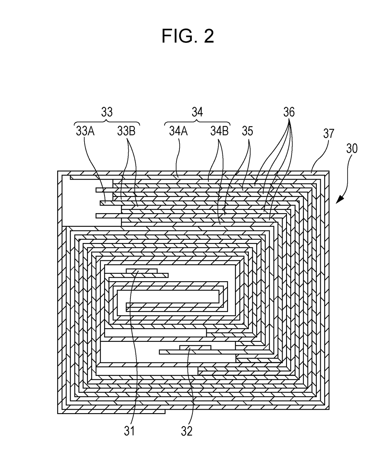
[0045]A nonaqueous electrolyte battery (battery) according to a first embodiment of the present disclosure will be described. FIG. 1 illustrates an exploded perspective configuration of the nonaqueous electrolyte battery according to the first embodiment of the present disclosure, and FIG. 2 illustrates an enlarged cross-section taken along line I-I in a wound electrode body 30 illustrated in FIG. 1.

[0046]In the nonaqueous electrolyte battery, mainly, a wound electrode body 30, to which a positive electrode lead 31 and a negative electrode lead 32 are attached, is accommodated inside a film-shaped exterior packaging member 40. A battery structure using the film-shaped exterior packaging member 40 is also referred to as a laminate film type. The nonaqueous electrolyte battery is, for example, a nonaqueous electrolyte secondary battery capable of being charged and discharged, and for example, a lithium ion secondary battery.

[0047]For example,...

second embodiment

2. Second Embodiment

[0192]In a second embodiment, description will be given to an example of a battery pack of a laminate film-type battery (nonaqueous electrolyte battery) provided with the same gel electrolyte layer as in the first embodiment.

[0193]The battery pack is a simple battery pack (also referred to as a soft pack). The simple battery pack is embedded in an electronic apparatus such as a smart phone. In the simple battery pack, a battery cell, a protective circuit, and the like are fixed with an insulating tape or the like, a part of the battery cell is exposed, and an output such as a connector to be connected to a main body of the electronic apparatus is provided.

[0194]An example of a configuration of the simple battery pack will be described. FIG. 4 is an exploded perspective view illustrating a configuration example of the simple battery pack. FIG. 5A is a schematic perspective view illustrating external appearance of the simple battery pack, and FIG. 5B is a schematic...

third embodiment

3. Third Embodiment

Example of Battery Pack

[0198]FIG. 6 is a block diagram illustrating an example of a circuit configuration in a case of applying the battery (hereinafter, appropriately referred to as a “secondary battery”) according to the first embodiment of the present disclosure to a battery pack. The battery pack includes an assembled battery 301, an exterior casing, a switch unit 304 including a charging control switch 302a and a discharging control switch 303a, a current detecting resistor 307, a temperature detecting element 308, and a control unit 310.

[0199]In addition, the battery pack includes a positive electrode terminal 321 and a negative electrode terminal 322. During charging, the positive electrode terminal 321 and the negative electrode terminal 322 are connected to a positive electrode terminal and a negative electrode terminal of a charger, respectively, to perform charging. In addition, during using of an electronic apparatus, the positive electrode terminal 32...


PUM

PropertyMeasurementUnit
thicknessaaaaaaaaaa
open-circuit voltageaaaaaaaaaa
porosityaaaaaaaaaa

Abstract

Provided is a battery in which an area density S (mg / cm2) of a positive electrode active material layer is 27 mg / cm2 or greater, and a porous film included in a separator has a structure satisfying the following Expressions.0.04≦Ri≦−0.07L−0.09×S+4.99Ri=τ2L / ε′ε′=[{(L×ε / 100)−Rz×0.46 / 3} / L]×100τ={(1.216×ε′Td×10−4) / L}0.5  (Expressions)

Description

CROSS REFERENCES TO RELATED APPLICATIONS[0001]The present application is a national stage of International Application No. PCT / JP2014 / 004280 filed on Aug. 21, 2014 and claims priority to Japanese Patent Application No. 2013-215006 filed on Oct. 15, 2013, the disclosure of which is incorporated herein by reference.BACKGROUND[0002]The present disclosure relates to a battery, a battery pack, an electronic apparatus, an electrically driven vehicle, an electrical storage device, and a power system.[0003]Recently, a lot of portable electronic apparatuses have appeared in the market, and a reduction in size and weight has been attempted. In a battery that is used as a power supply of each of the portable electronic apparatuses, miniaturization of the battery or effective use of an accommodation space inside the portable electronic apparatus has been demanded so as to realize the reduction in size and weight.[0004]As a battery that satisfies such demand, it is known that a lithium ion secon...

Claims


Application Information

Patent Timeline
Patent Type & Authority Patents(United States)
IPC IPC(8): H01M2/18H01M10/0525H01M10/04H01M4/525H01M4/131H01M4/62B60L11/18H02J7/00H01M10/42H01M10/0565H01M2/16H01M10/058H01M10/0587H01M4/02H01M10/052H01M50/202H01M50/211H01M50/417H01M50/426H01M50/443H01M50/449H01M50/451H01M50/457H01M50/469H01M50/489H01M50/491
CPCH01M2/18B60L11/1861H01M2/162H01M2/1653H01M4/131H01M4/525H01M4/622H01M4/625H01M10/0431H01M10/0525H01M10/0565H01M10/4257H02J7/0063H01M2/16H01M10/052H01M10/058H01M10/0587H01M2004/021H01M2004/028H01M2010/4278H01M2220/20H01M2220/30H01M2300/0082H02J7/0031H02J7/0042Y02E60/122Y02T10/7011H02J7/0029B60L58/15Y02T10/70H01M50/44H02J7/00308H02J7/00302H02J7/00304H02J7/00306H01M50/417H01M50/449H01M50/211H01M50/457H01M50/491H01M50/202H01M50/443H01M50/469H01M50/451H01M50/489H01M50/426Y02E60/10H01M4/366H01M2220/10H01M50/463H01M50/414H01M50/20
Inventor ABE, TOMOHIROTAKAGI, KENTARO
Owner MURATA MFG CO LTD
Why Eureka
Try Eureka