Percutaneous connector and associated methods of use

a percutaneous connector and connector technology, applied in the direction of coupling device connection, engagement/disengagement of coupling parts, prosthesis, etc., can solve the problems of shortening the life span, achieve lateral stabilization of the percutaneous connector, promote skin ingrowth, and reduce trauma

Active Publication Date: 2017-05-09
HEARTWARE INC
View PDF30 Cites 3 Cited by
  • Summary
  • Abstract
  • Description
  • Claims
  • Application Information

AI Technical Summary

Benefits of technology

[0010]One aspect of the percutaneous connector according to the disclosure may allow rotation of the cap with respect to the base to misalign the cap and base magnets to reduce the magnetic attraction between the cap and base. Further rotation of the cap with respect to the base can cause magnetic repulsion between the cap magnets and base magnets. Such rotation may make release of the cap from the base easier for the patient, thereby reducing patient discomfort during release.
[0012]The skirt extending from the base may comprise a flexible material and may have anchors associated with it. In at least one embodiment, the base is adapted to be implanted in a patient's skin and at least a portion of the base, positioned adjacent the patient's skin, can have a textured surface to promote skin ingrowth. In certain embodiments, this feature can help to reduce trauma and to provide lateral stabilization of the percutaneous connector.

Problems solved by technology

However, because of a shortage of donor hearts, most of these patients have a shortened life span characterized by frequent hospitalizations, severe physical disability, and death from congestive failure or cardiogenic shock, and do not survive long enough for a donor heart to become available.
The connection between the two portions must be strong enough to maintain the connection during normal use, but not so strong as to cause patient discomfort when disconnecting the portions.

Method used


Image

  • Percutaneous connector and associated methods of use
  • Percutaneous connector and associated methods of use
  • Percutaneous connector and associated methods of use

Examples


Embodiment Construction

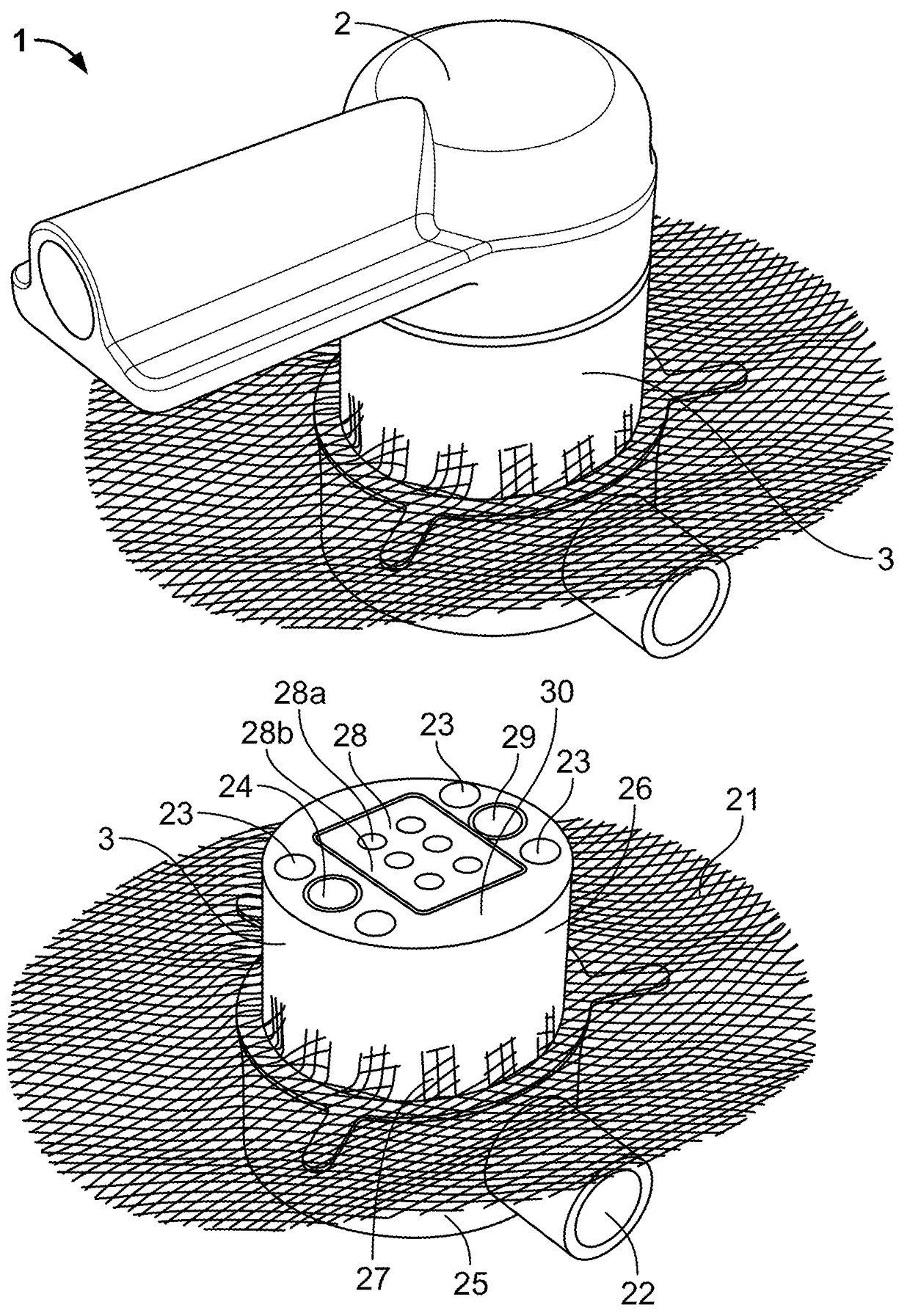
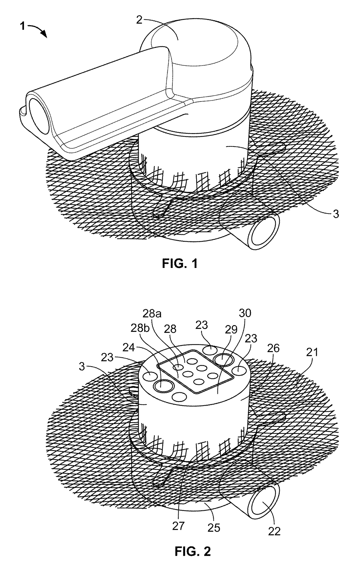
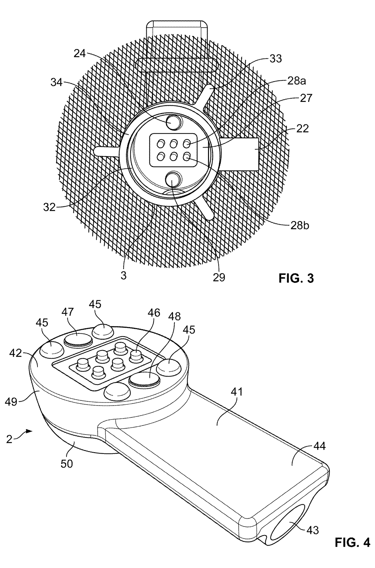
[0029]In a first embodiment, illustrated in FIGS. 1-7, a percutaneous connector 1 comprises a cap 2 and a base 3. As will be discussed more fully below, the percutaneous connector 1 is designed to provide a detachable electrical connection between an internally implanted device and an external controller or device. One type of internal device contemplated for use with the percutaneous connector is disclosed in U.S. Pat. No. 6,688,861, the entirety of which is incorporated by reference as if fully set forth herein. The external controller used with the percutaneous connector may be similar to that disclosed in pending U.S. application Ser. No. 12 / 602,914 filed May 24, 2010, the entirety of which is incorporated by reference herein as if fully set forth herein. Other internal devices (e.g. a transcutaneous energy transfer (TET) system, pacemaker, insulin pump, dialysis device, automatic implantable cardioverter defibrillator) and external controllers, and associated power sources, may...


PUM


Abstract

In one embodiment, the present invention includes a percutaneous skin connector including a base and a cap. The base has a channel extending through it and a plurality of base magnets are positioned around the channel and exposed at a base surface. A skirt which allows tissue ingrowth extends from the base to further secure the base to the patient. The connector also includes a cap with a bore extending through it and a plurality of cap magnets positioned around the bore and exposed at a cap surface. The base magnets and cap magnets attract and align the cap surface to the base surface. The connector further includes a release mechanism adapted to at least partially separate the cap from the base when the cap is rotated relative to the base and out of alignment with the base.

Description

CROSS-REFERENCE TO RELATED APPLICATIONS[0001]This application claims the benefit of the filing date of U.S. Patent Application No. 62 / 011,290, filed Jun. 12, 2014, and U.S. Patent Application No. 62 / 097,304 filed Dec. 29, 2014, the disclosures of which are hereby incorporated herein by reference.BACKGROUND OF THE INVENTION[0002]The present invention relates to an improved device and method for connecting a device implanted inside the body of a patient to an external controller.[0003]Thousands of heart patients who suffer from severe ventricular heart failure could benefit from cardiac transplantation. However, because of a shortage of donor hearts, most of these patients have a shortened life span characterized by frequent hospitalizations, severe physical disability, and death from congestive failure or cardiogenic shock, and do not survive long enough for a donor heart to become available.[0004]One medical device developed to aid these heart patients is a heart pump such as a vent...

Claims


Application Information

Patent Timeline
Patent Type & Authority Patents(United States)
IPC IPC(8): H01R13/62A61M1/10A61M39/02A61M1/12H01R13/52H01R13/24
CPCH01R13/6205A61M1/1008A61M1/127A61M39/0247A61M2039/0267A61M2039/0288A61M2205/3507A61M2205/3515H01R13/2421H01R13/5224A61M60/857A61M60/585A61M60/873A61M60/878A61M60/178A61M60/148
Inventor ANDRUS, LANCE LYNNCASTILLO, ANDRE
Owner HEARTWARE INC
Why Eureka
Try Eureka