Raw material fluid density detector

a fluid density and detector technology, applied in the direction of instruments, specific gravity measurement, investigation of moving fluids/granular solids, etc., can solve the problems of difficult connection and fixation, difficult to achieve air tightness performance, and difficult to achieve stable gas density measurement. , to achieve the effect of high air tightness, simple configuration, and simplified structure of light oscillation unit 5a and light detection unit 5b

Active Publication Date: 2017-05-16
UNIVERSITY OF TOKUSHIMA +1
View PDF19 Cites 14 Cited by
  • Summary
  • Abstract
  • Description
  • Claims
  • Application Information

AI Technical Summary

Benefits of technology

[0028]According to the present invention, at least one recess 17 is formed in the upper surface and the undersurface thereof, a fluid flow path 2a connecting a fluid inlet of the detector main body 2 to the recess 17, a fluid flow path 2b connecting the recesses 17 to each other, and a fluid flow path 2c connecting the recess 17 to a fluid outlet of the detector main body 2 are provided, the light oscillation unit 5a is disposed in at least one recess, and the remaining light detection units 5b are disposed in the remaining recesses in the detector main body 2. Thus, an in-line type raw material density detector with a very simple configuration can be achieved.
[0029]Moreover, the light oscillation unit 5a and the light detection unit 5b have the gasket type seal 6 attached into the gasket accommodation portion 17a, the first fixing flange 14 having the insertion recess 14b disposed facing the same, the second fixing flange 16 airtightly joined and fixed to the first fixing flange 14 by inserting and press-fitting the projection portion 16b into the insertion recess 14b, the sapphire light transmission plate 11a airtightly held between both the flanges, and the holding and fixing body 12 which pressurizes and fixes both the flanges 14 and 16 to the detector main body 2. Thus, the structure of the light oscillation unit 5a and the light detection unit 5b can be simplified and also high airtightness can be held.
[0030]Furthermore, the light transmission window 11 is formed of sapphire, and thus, even in the case of a depositing, reactive, and corrosive fluid, the light transmittance does not decrease and stable high-accuracy density measurement can be achieved.
[0031]Moreover, since the gasket type seal is used, mixing of impurities into the fluid can be completely eliminated as compared with other seal structures employing synthetic resin seal materials, silver brazing materials, gold brazing materials, and the like.
[0032]In addition, the light transmission window which is the plate member 11 containing a brittle fracture material is sandwiched between the first fixing flange 14 and the second fixing flange 16 and also both the flanges are airtightly joined and fixed, and further both the joined and fixing flanges, to which the light transmission window is attached, are airtightly inserted into the recess 17 with the holding and fixing body 12 fixed to the main body 2, and thus the light transmission window can be airtightly, easily, and firmly held and fixed without using a seal material.
[0033]Thus, the raw material fluid density detector of the present invention demonstrates outstanding effects in terms of reducing the size and the cost of facilities, maintaining airtightness, securing of stability of density measurement accuracy, maintaining of high gas purity, and the like.

Problems solved by technology

However, there are problems that it is not easy to secure the airtightness of a connecting portion between the optical cell 27 and the pipeline 32 (or the pipeline 31) and, for example, it is not easy to achieve connection and fixation having high airtightness by screw connection and a flange connection method employing usual packing materials and seal materials, which makes it actually impossible to achieve securing of airtightness performance (External leak of 1×10⁻¹° Pa·m3 / sec or less) demanded in the field of a semiconductor manufacturing apparatus.
When the transparency changes with time, the stable gas density measurement becomes difficult to achieve.
Thus, when measuring the density of an organic raw material gas having high corrosiveness or high deposition properties, the light transmission window is corroded or the transparency decreases at an early stage due to the deposition of the raw material.
Thus, a problem that stable measurement of the raw material gas density cannot be performed has remained unsolved.
However, materials, such as synthetic resin seal materials, silver brazing, and gold brazing, in the optical cell 27 have risk of serving as emission sources which emits gas and particles contained in each material itself into the organic raw material gas, which actually poses a problem of a reduction in gas purity due to the emission of particles.
Thus, in the gas supply systems for semiconductor manufacturing, the use of silver brazing or gold brazing is not desirable.
As described above, the use of the former optical-analysis-type density meter makes it difficult to reduce the size and the cost of facilities and also poses a large number of problems in maintaining gas airtightness, securing of stability of density measurement accuracy, maintenance of high gas purity, and the like.
Particularly in the case of an organic raw material gas, the problems, such as the reduction in the transparency of the light transmission window resulting from the corrosiveness thereof, the reduction in the gas purity due to the seal members, the securing of airtightness, and the like, need to be solved as soon as possible.

Method used


Image

  • Raw material fluid density detector
  • Raw material fluid density detector
  • Raw material fluid density detector

Examples


Embodiment Construction

[0045]Hereinafter, embodiments of the present invention are described in detail with reference to the drawings.

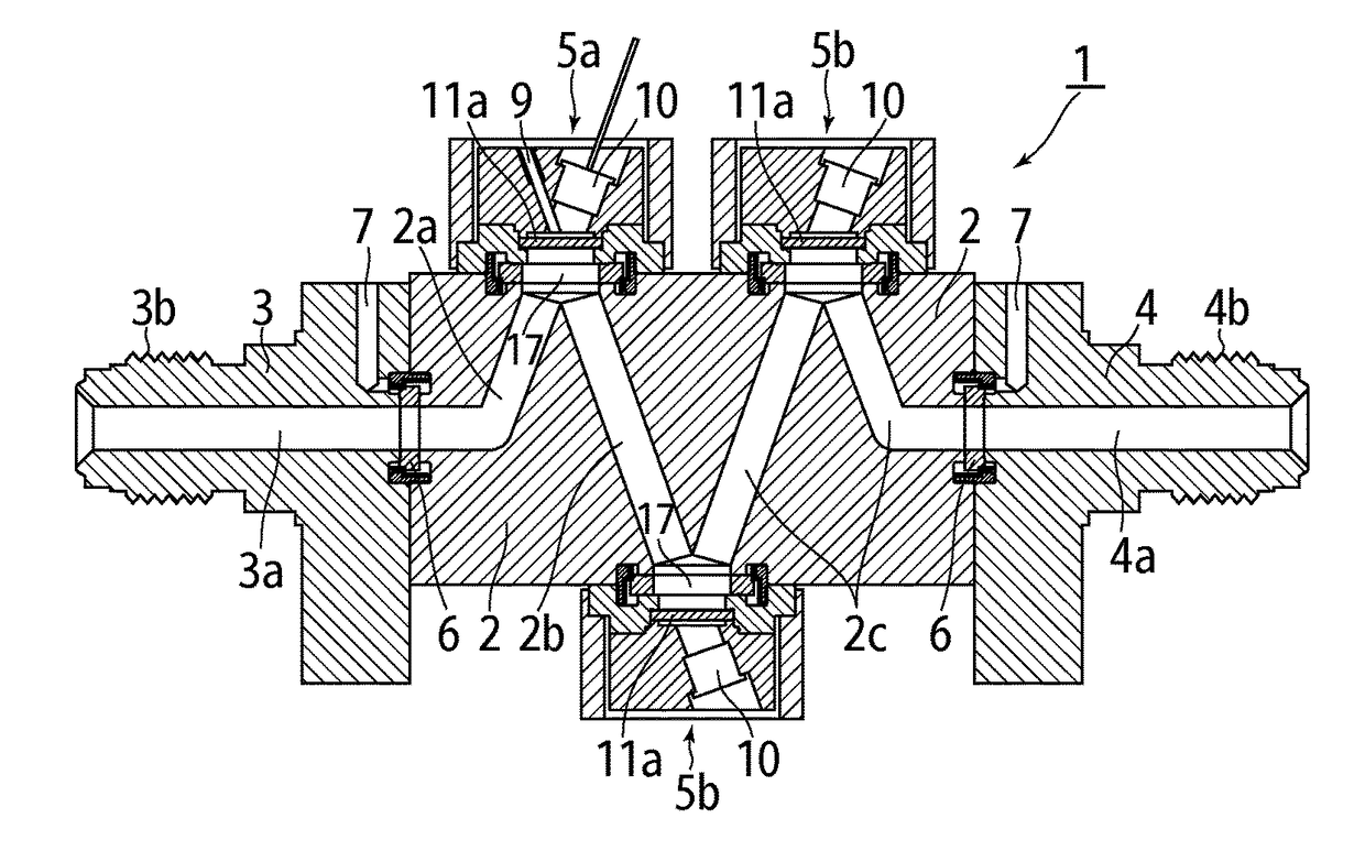
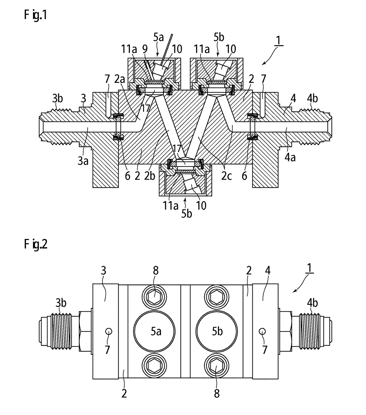
[0046]FIG. 1 and FIG. 2 illustrate a raw material fluid density detector 1 according to a first embodiment of the present invention, and the raw material fluid density detector 1 is configured from a detector main body 2, an inlet block 3 and an outlet block 4 fixed to both sides thereof, a light oscillation unit 5a and a light detection unit 5b provided in parallel on the upper surface side of the detector main body 2, a light detection unit 5b provided on the undersurface side of the detector main body 2, and the like.

[0047]The detector main body 2, the inlet block 3, and the outlet block 4 are formed of stainless steel and the like, and fluid flow paths 2a, 2b, 2c, 3a, and 4a are provided in a communication manner. The inlet block 3 and the outlet block 4 are airtightly fixed to both sides of the detector main body 2 with bolts (not illustrated) via gasket type seals 6. ...


PUM

PropertyMeasurementUnit
forceaaaaaaaaaa
thickaaaaaaaaaa
thicknessaaaaaaaaaa

Abstract

This invention is related to an optical-analysis-type raw material fluid density detector including a detector main body and a light oscillation unit and a light detection unit that are provided on the upper surface or the under surface of the detector main body, in which the detector main body has at least one recess formed in the upper surface and the under surface, a fluid flow path connecting a fluid inlet of the detector main body to the recess, a fluid flow path connecting the recesses to each other, and a fluid flow path connecting the recess to a fluid outlet of the detector main body; the light oscillation unit is disposed in the recess that is closest to the inlet; and light detection units are disposed in the remaining recesses.

Description

TECHNICAL FIELD[0001]The present invention relates to an improvement of a process fluid density meter for use in a raw material fluid supply system for a semiconductor manufacturing apparatus and the like, and particularly relates to an in-line optical-analysis-type raw material fluid density detector which achieves a size reduction and an in-line type of a sensor unit of a density meter and also enables maintenance of high transparency of a light transmission window and high cleanliness (resistance to particles) of the inside of a sensor which are stable over a long time period even in the case of a raw material fluid having high deposition properties, high photoreactivity, and corrosiveness.BACKGROUND ART[0002]The raw material fluid supply system for the semiconductor manufacturing apparatus and the like needs to supply a process raw material fluid with a stable density to a processing device in terms of improving the quality of a semiconductor product.[0003]Thus, in the former ra...

Claims


Application Information

Patent Timeline
Patent Type & Authority Patents(United States)
IPC IPC(8): G01N9/00G01N21/05G01N9/24G01N21/59G01N21/33G01N21/85
CPCG01N9/00G01N9/24G01N21/05G01N21/59G01N21/33G01N21/85G01N2201/08
Inventor DEGUCHI, YOSHIHIRONAGASE, MASAAKIDOHI, RYOUSUKEIKEDA, NOBUKAZUNISHINO, KOUJIYAMAJI, MICHIOYAKUSHIJIN, TADAYUKI
Owner UNIVERSITY OF TOKUSHIMA
Why Eureka
Try Eureka