Wireless resonant electric field power transfer system and method using high Q-factor coils

a technology of resonant electric field and coil, which is applied in the direction of electric energy management, inductance, electric devices, etc., can solve the problems of inefficient radiative energy transfer, inability to transmit data, and large majority of power radiated, so as to prevent electromagnetic field leakage and increase electric field strength

a technology of resonant electric field and coil, which is applied in the direction of electric energy management, inductance, electric devices, etc., can solve the problems of inefficient radiative energy transfer, inability to transmit data, and large majority of power radiated, so as to prevent electromagnetic field leakage and increase electric field strength

US9653948B2Active Publication Date: 2017-05-16SOLACE POWER INC

Image

  • Wireless resonant electric field power transfer system and method using high Q-factor coils
  • Wireless resonant electric field power transfer system and method using high Q-factor coils
  • Wireless resonant electric field power transfer system and method using high Q-factor coils

Examples


Embodiment Construction

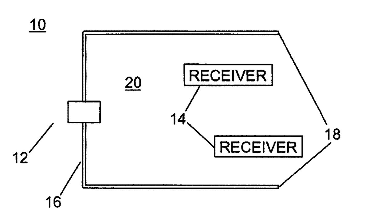
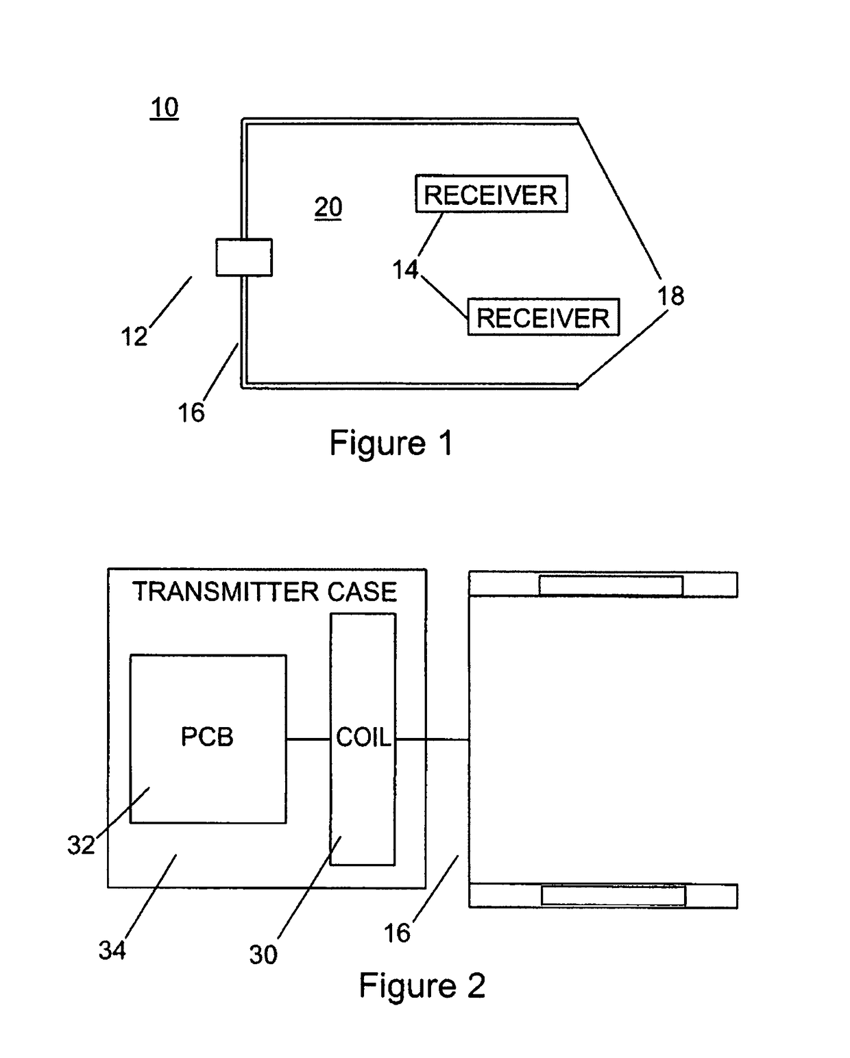
[0081]Turning now to FIG. 1, a wireless electric field power transmission system is shown and is generally identified by reference numeral 10. As can be seen, power transmission system 10 comprises a transmitter 12 comprising a transmitter antenna 16 coupled and a plurality of receivers 14. Although only two receivers 14 are shown, it will be appreciated that this is for ease of illustration only. The power transmission system 10 may comprise more or fewer receivers 14. The transmitter antenna 16 comprises two approximately parallel, laterally spaced conductors 18 defining a volume 20 between them. The conductors 18 are elongate and generally rectangular and are oriented such that major surfaces of the conductors face one another. In this embodiment, each conductor 18 is formed of aluminum foil tape due to its flexibility, low cost and availability. Each receiver 14 can be positioned within the volume 20 to harvest power wirelessly as a result of an electric field generated within t...


PUM


Abstract

A wireless electric field power transmission system comprises: a transmitter comprising a transmitter antenna, the transmitter antenna comprising at least two conductors defining a volume therebetween; and at least one receiver, wherein the transmitter antenna transfers power wirelessly via electric field coupling when the at least one receiver is within the volume.

Description

CROSS REFERENCE TO RELATED APPLICATIONS[0001]This application claims the benefit of U.S. Provisional Application No. 61 / 532,092 filed Sep. 7, 2011, the content of which is incorporated by reference in its entirety.FIELD OF THE INVENTION[0002]The present invention relates generally to wireless power transmission and in particular, to a wireless electric field power transmission system and method.BACKGROUND OF THE INVENTION[0003]A variety of radiative, or far-field, and non-radiative, or near-field, energy or power transfer techniques are known. For example, radiative wireless information transfer using low-directionality antennas, such as those used in radio and cellular communications systems and home computer networks, may be considered wireless energy transfer. As will be appreciated, this type of radiative energy transfer is inefficient because only a small portion of the supplied or radiated power, namely, that portion in the direction of, and overlapping with, the receiver is p...

Claims


Application Information

Patent Timeline
16 May 2017
Publication
US9653948B2
IPC
H02J50/05; H03L7/081; H01Q1/22; H01Q1/27; H01Q1/32; B60L11/18; H02J7/00; H03F3/30; H03F3/24; H03F3/195; H03F1/56; H02J50/27; H02J50/40; H02J50/23; H02J50/12; H02J7/02; H01Q7/08; H04B5/00; H02J50/80; H02J50/60
CPC
H02J50/40; B60L11/182; B60L11/1833; H01Q1/2225; H01Q1/273; H01Q1/3216; H01Q7/08; H02J7/0042
Inventors
POLU, NAGESH; ALAM, MD. JAHANGIR