Method and system of beam injection to charged particle storage ring

a technology of charged particle and storage ring, which is applied in the direction of magnetic resonance accelerators, accelerators, electrical apparatuses, etc., can solve the problems of high cost, increased power source capacity, and difficult adjustment, and achieves increased x-ray intensity, low cost, and increased average current value

Inactive Publication Date: 2017-05-16
PHOTON PRODN LAB +1
View PDF17 Cites 0 Cited by
  • Summary
  • Abstract
  • Description
  • Claims
  • Application Information

AI Technical Summary

Benefits of technology

[0015]According to the present invention, while an excitation current of continuous sinusoidal wave is flowing in the perturbating device, the charged particle beam generated by the DC accelerator is continuously injected, whereby a larger current can be stored in the storage ring than when a charged particle beam generated by a microtron or the like is injected. For example, a large current of 10 mA in average can be stored. Therefore, when the storage ring is used as an X-ray generator, for example, the X-ray intensity can be increased than in the past. Further, the X-ray can be generated continuously for a longer time period than when a charged particle beam generated by a microtron or the like is injected.
[0016]Though the electron beam from the DC accelerator has a low energy of smaller than 1 MeV (for example, 400 to 800 keV), it can be output for a long period of time and, therefore, average current value can be increased. The electron beam can be supplied as pulses having 25% duty cycle.
[0017]As the DC accelerator, a high-voltage generator used for an X-ray tube or the like can be used and, therefore, it can be manufactured at a low cost.
[0018]Further, since the kinetic energy is smaller than 1 MeV, the amount of generated fluorescent X-ray increases and, hence, the extracting unit can be provided closer to the X-ray source (target) than the extracting unit for bremsstrahlung. Therefore, the structure for shielding the X-ray output from the storage ring can be made relatively compact. Particularly for the magnified imaging, the X-ray shielding structure can be made significantly smaller than when the bremsstrahlung is used for the same magnification.
[0019]As an apparatus allowing magnified imaging of high magnification, a micro-focus X-ray tube that focuses an electron beam on an X-ray target has been known. The present invention is also superior to this. Average current value of micro-focus X-ray is about 1 μA at most, and its limit is about 10 μA (limit of cooling). It is difficult for the micro-focus X-ray tube to use a current of 1 mA or higher as in the present invention. It is noted that the electron beam can be converged to a few μm in the micro-focus X-ray tube. The value, however, is the half value width of a bell-shaped intensity distribution, and the border of X-ray source is unclear. In contrast, in the present invention using the storage ring, what is necessary is to fabricate the target with the size of μm order, and the border of X-ray source is clear. Therefore, it is more preferable as a point light source for the magnified imaging.

Problems solved by technology

This adjustment is very difficult, as it is influenced by the signal jitter (time jitter).
For this purpose, however, power source capacity must be increased, which is costly.

Method used


Image

  • Method and system of beam injection to charged particle storage ring
  • Method and system of beam injection to charged particle storage ring
  • Method and system of beam injection to charged particle storage ring

Examples


Embodiment Construction

[0029]In the following embodiments, the same portions are denoted by the same reference characters. Their names and functions are also the same. Therefore, detailed description thereof will not be repeated.

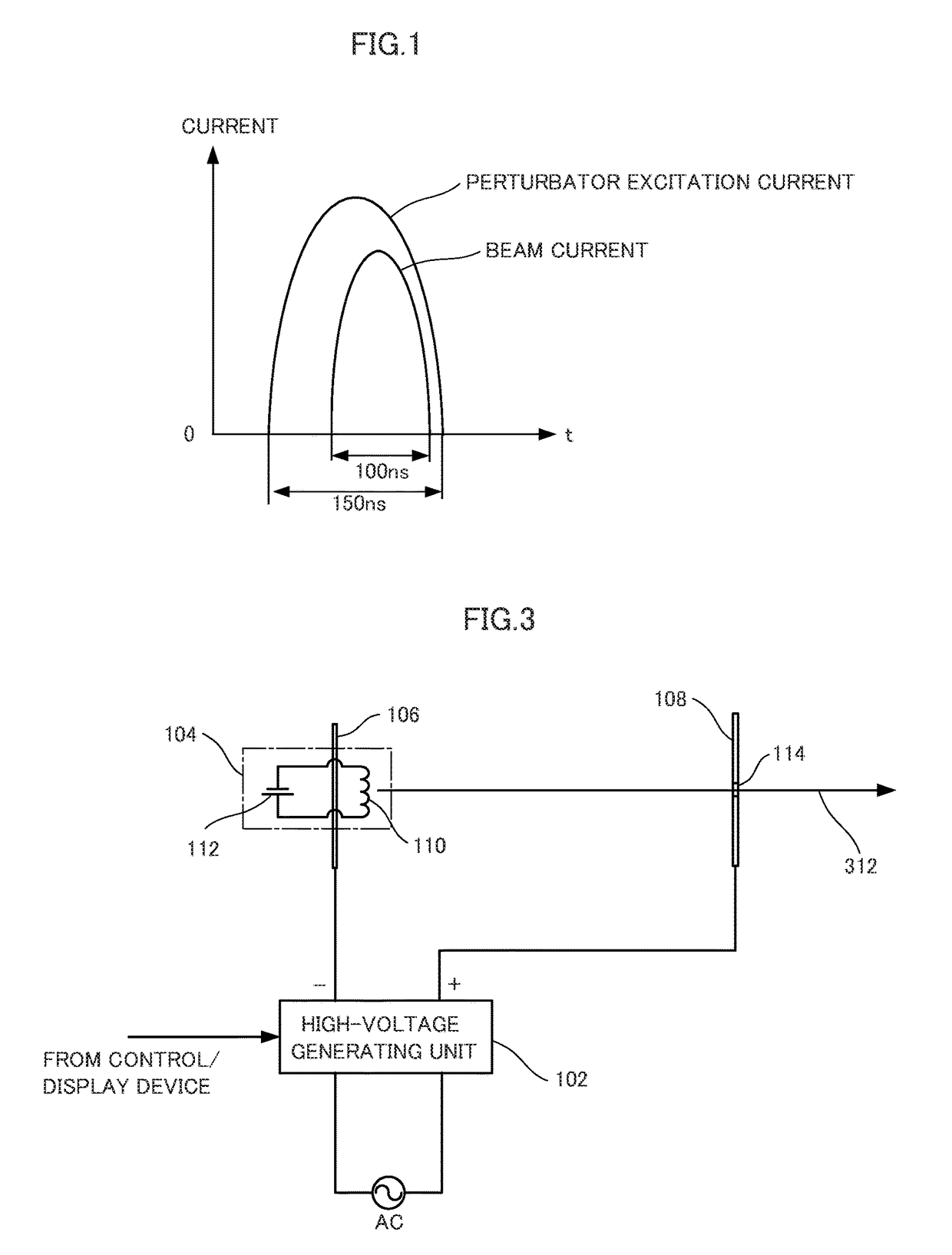
[0030]The charged particle storage system in accordance with an embodiment of the present invention is a system for storing electrons, including an electron beam generating unit, a storage ring unit using a weak convergence synchrotron, and a control unit. As the electron beam generating unit, a known high-voltage generator used, for example, for an X-ray tube, is used.

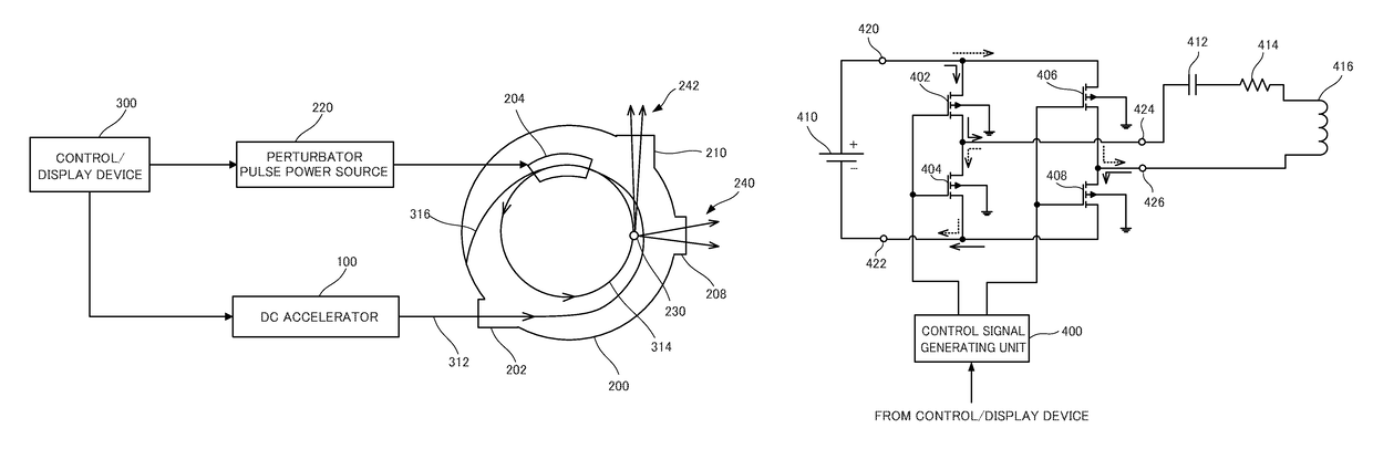
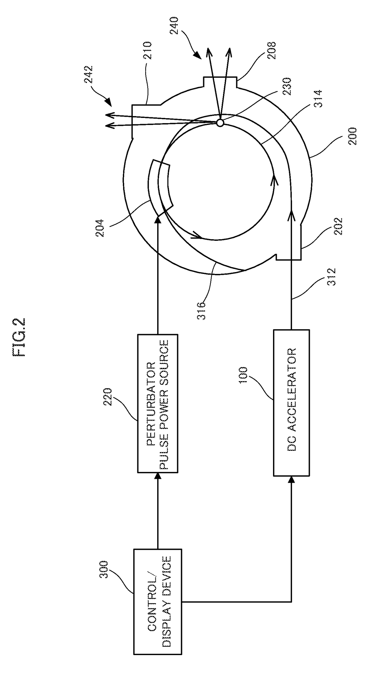
[0031]Referring to FIG. 2, the electron beam generating unit includes a DC accelerator 100. The storage ring unit includes a storage ring body 200, a beam injecting unit 202, a perturbator 204, a fluorescent X-ray extracting unit 208, a bremsstrahlung extracting unit 210 and a perturbator pulse power source 220. The control unit includes a control / display device 300 for controlling various units (including DC accele...


PUM


Abstract

The charged particle storage system includes: a storage ring circulating, by a perturbating device, charged particles injected from outside; a power source supplying an electric current to the perturbating device; and a charged particle beam generating device. The charged particle beam generating device includes a DC accelerator that generates a constant voltage to accelerate electrons and thereby generates a beam of the electrons. While a current having its current intensity changing in a sinusoidal wave is caused to flow through the perturbating device continuously for at least 10 μs by a power source, an electron beam output from the charged particle beam generating device is injected to the storage ring continuously for at least 10 μs. Thus, a current larger than that stored by the conventional resonance injection method can be stored in the storage ring, and an X-ray having higher intensity can be generated.

Description

TECHNICAL FIELD[0001]The present invention relates to a method of continuously injecting a beam of charged particles to a storage ring for circulating and thereby storing charged particles such as electrons, as well as to a system thereof.BACKGROUND ART[0002]In a charged particle circulation apparatus (hereinafter also referred to as a storage ring) such as a synchrotron, perturbation is generated by using a perturbating device such as a perturbator, and thereby charged particles injected to the circulation apparatus are taken to a stable orbit (hereinafter also simply referred to as an orbit). After the particles are taken to the stable orbit, the charged particles circulating in the stable orbit may be accelerated using a high-frequency acceleration cavity.[0003]As an example of a radiation light generator (X-ray generator) using an electron storage ring, MIRRORCLE radiation light generator has been known. MIRRORCLE radiation light generator is a small-size radiation light generat...

Claims


Application Information

Patent Timeline
Patent Type & Authority Patents(United States)
IPC IPC(8): H05H7/08H05H13/04
CPCH05H7/08H05H13/04H05H2007/085
Inventor YAMADA, HIRONARI
Owner PHOTON PRODN LAB
Why Eureka
Try Eureka