
Unimorph-type ultrasound probe

a technology of ultrasound probes and morphs, applied in the field of unimorph-type ultrasound probes, can solve the problems of difficult to shape bulk piezoelectric materials, difficult to reduce side lobes with respect, and unclear ultrasound images, etc., to achieve the effect of reducing side lobes and facilitating manufacturing

Active Publication Date: 2017-05-23
FUJIFILM CORP
View PDF18 Cites 3 Cited by
  • Summary
  • Abstract
  • Description
  • Claims
  • Application Information

AI Technical Summary

Benefits of technology

The invention aims to solve problems in ultrasound probe design by providing a unimorph-type probe that is easier to make and minimizes side lobe in the minor axis direction.

Problems solved by technology

An ultrasonic echo from a reflector positioned on the side lobe is received along with an ultrasonic echo due to the main lobe, which causes a problem in that an ultrasound image becomes unclear.
However, since only one transducer exists in a minor axis direction, it is not possible to reduce a side lobe with respect to the minor axis direction using the apodization.
However, it is not easy to shape a bulk piezoelectric substance made of a conventional inorganic material so as to have a rhombic planar shape.
Although an attempt to realize a piezoelectric substance having a rhombic planar shape using a dicing saw was made, it was necessary to carry out special cutting in a direction inclined with respect to the arrangement direction of the piezoelectric substances, and a lot of labor, time, and cost were required.

Method used


Image

  • Unimorph-type ultrasound probe
  • Unimorph-type ultrasound probe
  • Unimorph-type ultrasound probe

Examples


embodiment 1

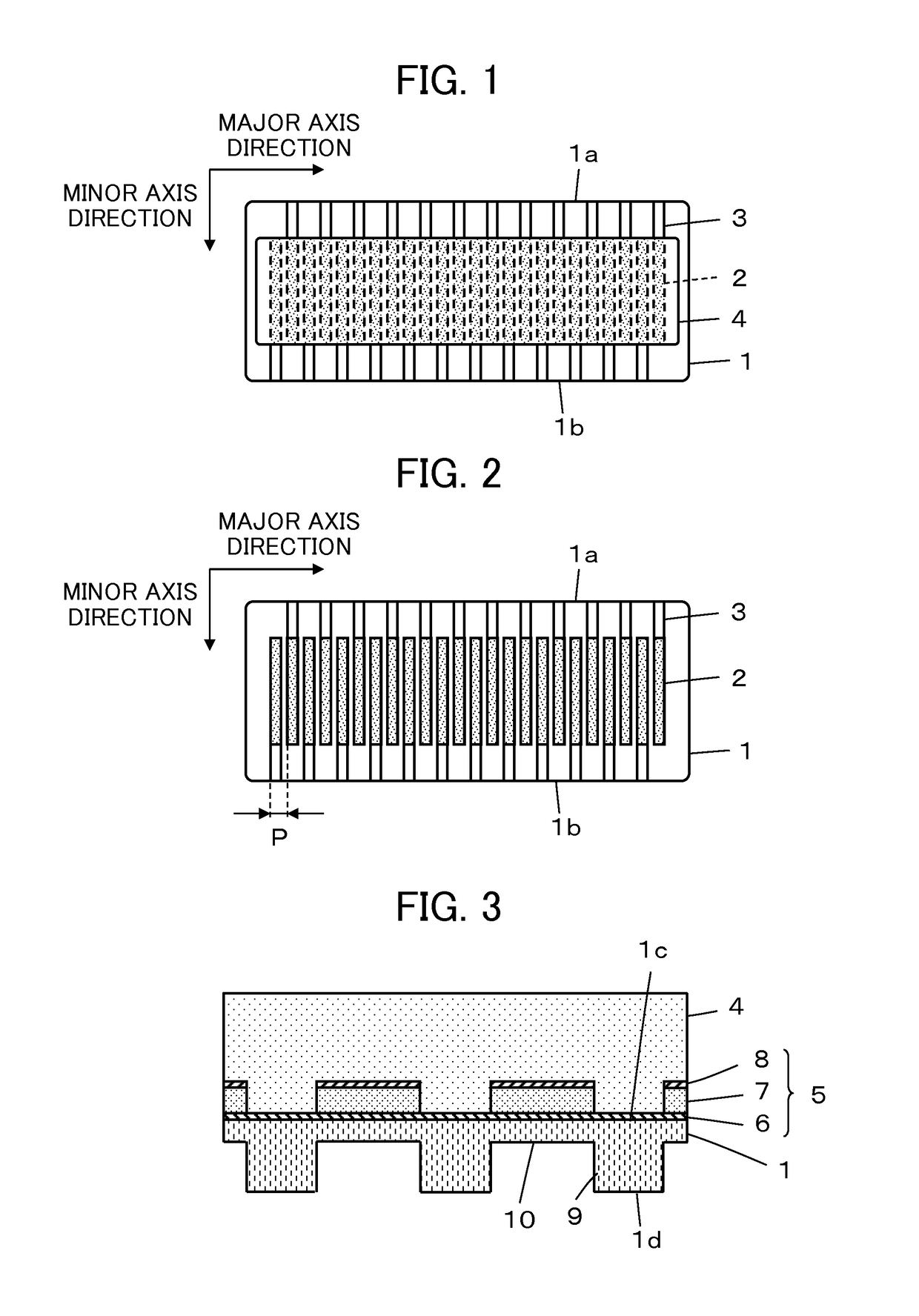
[0022]FIG. 1 shows the constitution of a unimorph-type ultrasound probe according to Embodiment 1 of the present invention.

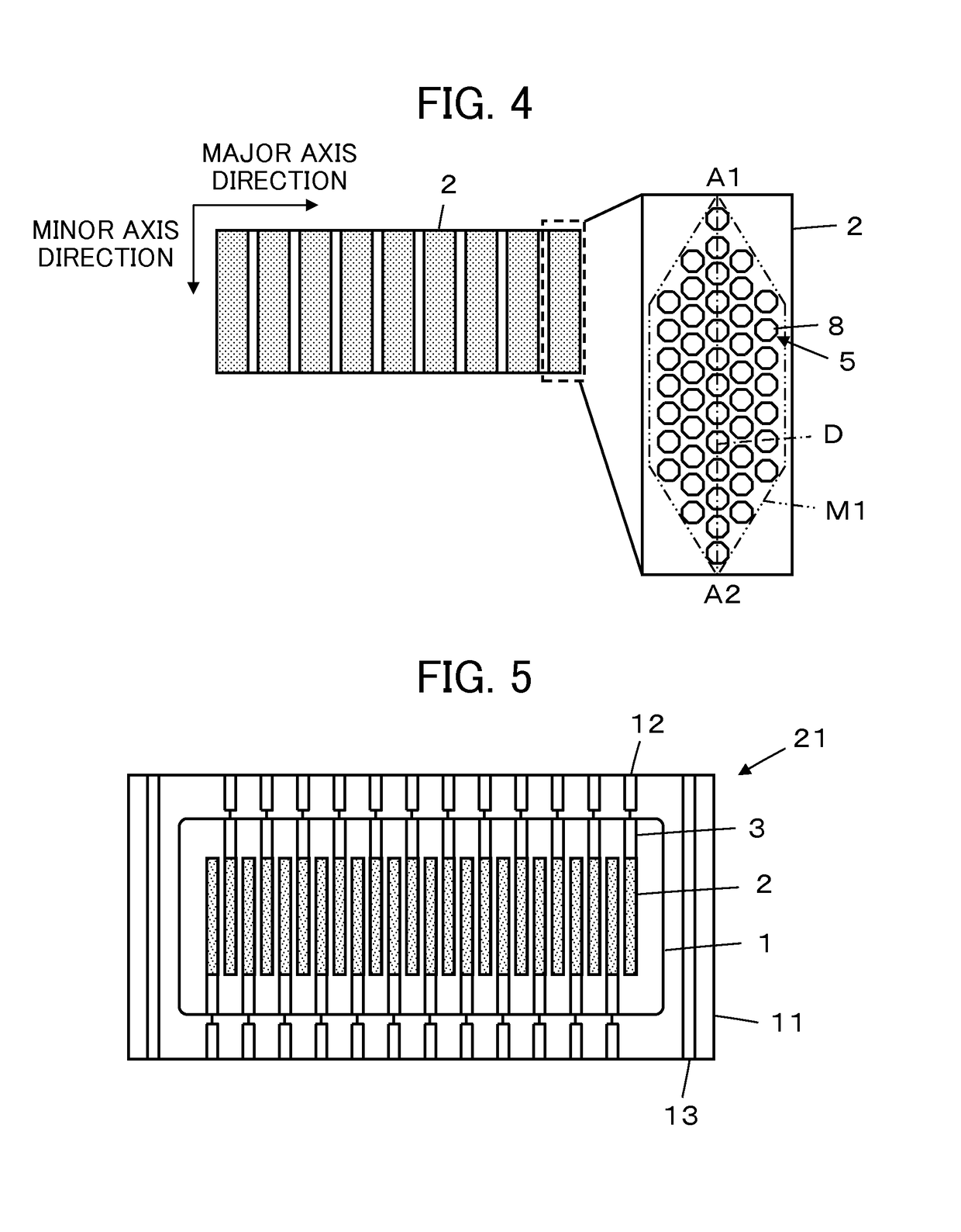
[0023]In the unimorph-type ultrasound probe, a plurality of piezoelectric element regions 2 are formed on a surface of a substrate 1. Each of the piezoelectric element regions 2 extends in the form of a strip in a minor axis direction (elevation direction), and is arranged at a small interval in a major axis direction (azimuth direction). A plurality of minute piezoelectric element portions are formed so as to be arranged in each of the piezoelectric element regions 2. Furthermore, each of the piezoelectric element regions 2 is connected to a corresponding lead-out electrode 3 in the minor axis direction. The lead-out electrodes 3 alternately extend in any one of a pair of lateral edges 1a and 1b of the substrate 1 so as to ensure an arrangement pitch therebetween.

[0024]Moreover, a covering layer 4 is disposed on the substrate 1 so as to cover all of the piezoel...

embodiment 2

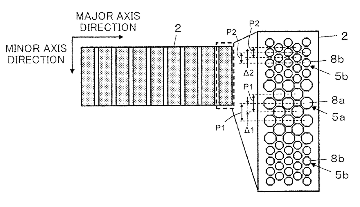
[0045]FIG. 8 shows a plurality of minute piezoelectric element portions formed in a piezoelectric element region 2 of a unimorph-type ultrasound probe according to Embodiment 2.

[0046]In Embodiment 1 described above, although the plurality of minute piezoelectric element portions 5 in the piezoelectric element region 2 have the same size, and the number of piezoelectric element portions 5 in the minor axis direction is changed, the unimorph-type ultrasound probe according to Embodiment 2 has a plurality of first piezoelectric element portions 5a having a first diameter and a plurality of second piezoelectric element portions 5b having a second diameter smaller than the first diameter, which are arranged in each of the piezoelectric element regions 2. All of the first piezoelectric element portions 5a and the second piezoelectric element portions 5b have a regular octagonal planar shape, and the diameters of the first piezoelectric element portions 5a and the second piezoelectric elem...


PUM

PropertyMeasurementUnit
diameteraaaaaaaaaa
ultrasound imagesaaaaaaaaaa
ultrasoundaaaaaaaaaa

Abstract

A unimorph-type ultrasound probe has a plurality of piezoelectric element regions which extend in a minor axis direction and are arranged at a predetermined arrangement pitch in a major axis direction, a plurality of minute piezoelectric element portions are formed so as to be arranged in each piezoelectric element region, the size of the plurality of minute piezoelectric element portions is changed in the minor axis direction, the plurality of minute piezoelectric element portions are arranged such that the size of the piezoelectric element portions in both end portions in the minor axis direction becomes smaller than the size of the piezoelectric element portions in a central portion in the minor axis direction, and ultrasonic waves having different frequencies are radiated from the piezoelectric element portions having different sizes.

Description

CROSS-REFERENCE TO RELATED APPLICATIONS[0001]This application is a Continuation of PCT International Application No. PCT / JP2014 / 057812 filed on Mar. 20, 2014, which claims priority under 35 U.S.C. §119(a) to Japanese Patent Application No. 2013-069657 filed on Mar. 28, 2013. The above application is hereby expressly incorporated by reference, in its entirety, into the present application.BACKGROUND OF THE INVENTION[0002]The present invention relates to a unimorph-type ultrasound probe, and in particular, to a unimorph-type ultrasound probe for achieving reduction in a side lobe in a minor axis direction.[0003]Conventionally, in the medical field, an ultrasound diagnostic apparatus using ultrasound images has been put to practical use. Generally, in this type of ultrasound diagnostic apparatus, an ultrasonic beam is transmitted toward the inside of a subject from an ultrasound probe, an ultrasonic echo from the subject is received by the ultrasound probe, and the received signal is e...

Claims


Application Information

Patent Timeline
Patent Type & Authority Patents(United States)
IPC IPC(8): H01L41/04B06B1/06B01B1/06H10N30/80
CPCB06B1/0622
Inventor YAMAMOTO, KATSUYA
Owner FUJIFILM CORP
Learn More