Eureka AIR delivers breakthrough ideas for toughest innovation challenges, trusted by R&D personnel around the world.

Exhaust heat recovery device for internal combustion engine and exhaust heat recovery method for internal combustion engine

a heat recovery device and exhaust heat technology, which is applied in steam use, machines/engines, mechanical equipment, etc., can solve the problems of low heat energy, inability to stably output power in a state, and exhaust heat energy that can be used, and achieve the effect of efficient use of exhaust heat from internal combustion engines

Active Publication Date: 2017-05-23
ISUZU MOTORS LTD
View PDF16 Cites 2 Cited by
  • Summary
  • Abstract
  • Description
  • Claims
  • Application Information

AI Technical Summary

Benefits of technology

[0011]The present invention has been made in view of the problems described above, and an object of the present invention is to provide an exhaust heat recovery device for an internal combustion engine and an exhaust heat recovery method for an internal combustion engine, which can level power outputted from an expander without reduction of the power even in the case where an evaporator cannot vaporize a working medium, for example, immediately after start-up and immediately before stop, or during a low-load operation of an internal combustion engine, and whereby can efficiently use the exhaust heat from the internal combustion engine.
[0019]With this configuration, the leveling line that levels the output of the power when the expander cannot output predetermined power only with a working medium flowing out from an evaporator is provided, and a surplus working medium is discharged from the steam accumulator to drive the expander even in the case where the evaporator cannot vaporize a working medium, for example, immediately after start-up and immediately before stop, or during a low-load operation of an internal combustion engine. This makes it possible to prevent a reduction in power, and to level the power outputted by the expander, whereby it is possible to efficiently use exhaust heat from the internal combustion engine. Furthermore, by using the leveled power to drive the internal combustion engine, it is possible to improve fuel efficiency.
[0029]In addition, in the exhaust heat recovery device for an internal combustion engine described above, the steam accumulator is configured to include a heat storage tube having both ends closed and having a heat storage material enclosed therein, this heat storage material melting at a temperature of not less than 80° C. and not more than 150° C. With this configuration, an effect of latent heat and heat storage is given in addition to a configuration of storing pressure that a normal accumulator has and a configuration of storing heat with sensible heat of a working medium. Thus, it is possible to reduce the size while maintaining the same heat capacity, and suppress an increase in weight. This makes it possible to improve mountability to vehicles.
[0041]According to the present invention, it is possible to level the power outputted from the expander without reduction of the power even in the case where the evaporator cannot vaporize the working medium, for example, immediately after start-up and immediately before stop, or during a low-load operation of an internal combustion engine, whereby it is possible to efficiently use exhaust heat from the internal combustion engine. Furthermore, by using the power, for example, as assistance in driving the internal combustion engine, it is possible to improve fuel efficiency of the internal combustion engine.

Problems solved by technology

Thus, it is not possible to stably output the power in a state where exhaust heat energy is low, for example, immediately after the engine has started, immediately before the engine stops, or during a low-load operation, and an effect thereof on a practical fuel efficiency is merely several percents.
However, with these devices, the amount of exhaust heat energy that can be used is limited to the amount of the exhaust heat energy that the steam accumulator can store, and hence, the exhaust heat energy from the engine cannot be efficiently used.
In addition, if the capacity of the steam accumulator is increased, mountability to a vehicle deteriorates accordingly.

Method used


Image

  • Exhaust heat recovery device for internal combustion engine and exhaust heat recovery method for internal combustion engine
  • Exhaust heat recovery device for internal combustion engine and exhaust heat recovery method for internal combustion engine
  • Exhaust heat recovery device for internal combustion engine and exhaust heat recovery method for internal combustion engine

Examples


Embodiment Construction

[0050]Hereinbelow, an exhaust heat recovery device for an internal combustion engine and an exhaust heat recovery method for an internal combustion engine according to an exemplary embodiment of the present invention will be described with reference to the drawings. Note that dimensions in the drawings are changed so that configurations are easily recognized, and ratios of thicknesses, widths, lengths, or other dimensions of each member and each part are not always equal to those actually manufactured.

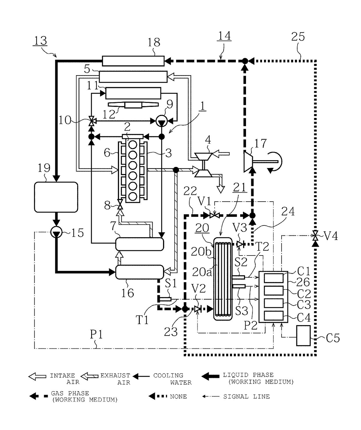
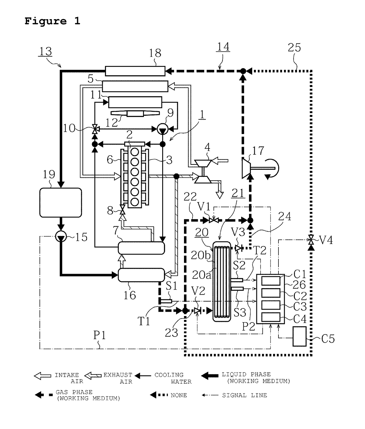
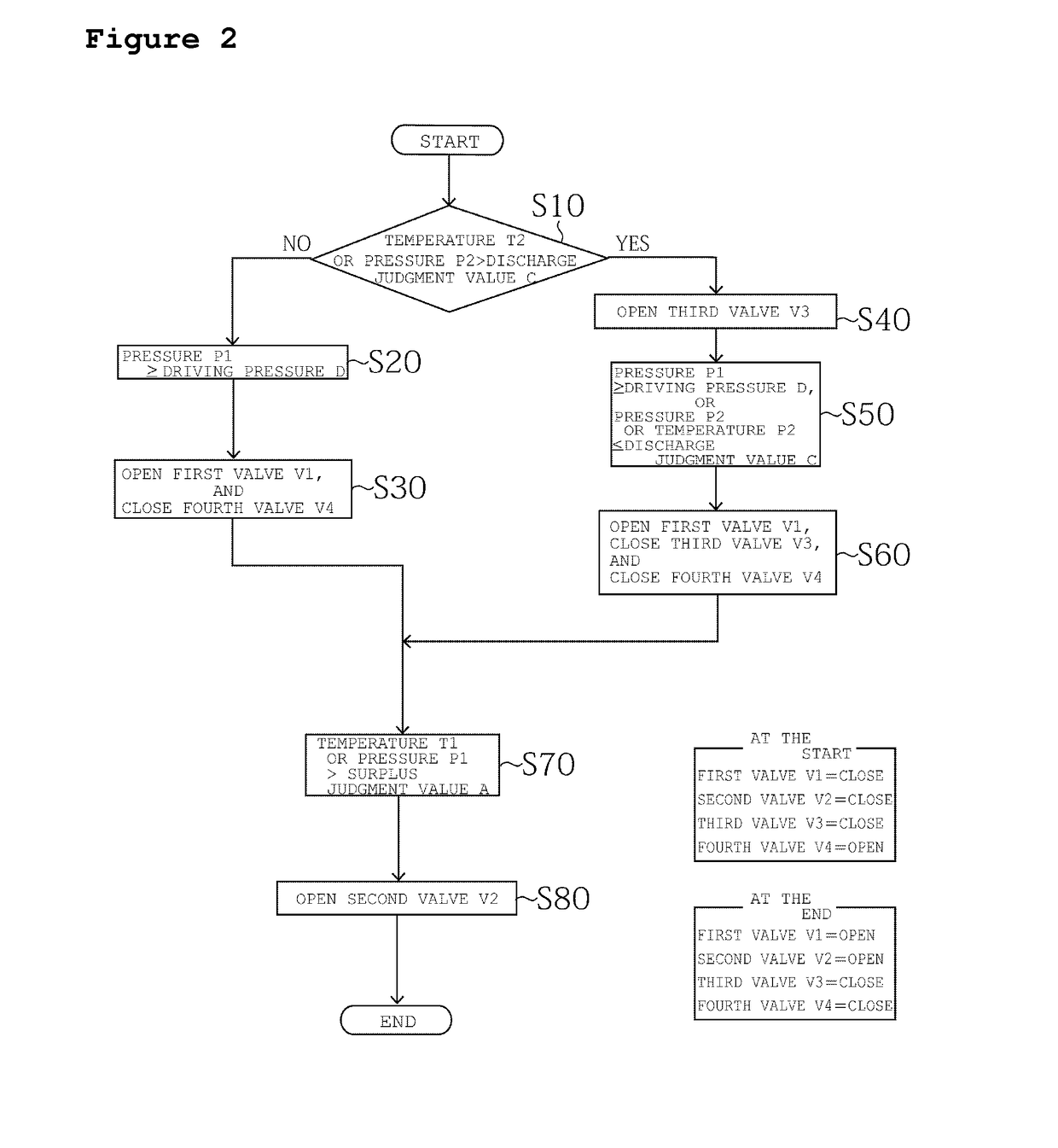
[0051]In the following exemplary embodiment, description will be made by using a diesel engine as an example. However, application of the present invention is not limited to the diesel engine, and can be applied also to a gasoline engine. Furthermore, the number of cylinders or arrangement of cylinders is not limited. An engine 1 illustrated in FIG. 1 to FIG. 4, and FIG. 7 is configured such that exhaust gas emitted from an engine main body 2 is discharged from an exhaust manifold 3 to...


PUM


Abstract

An exhaust heat recovery device for an engine including a Rankine cycle, including a steam accumulator that stores a surplus of a working medium for driving a turbine, and a leveling line that discharges the stored surplus working medium from the steam accumulator to the turbine, when the turbine cannot output predetermined power only with the working medium flowing out from a boiler, and levels the power outputted from the turbine. Since the power outputted from the turbine can be leveled without reduction of the power, even if the working medium cannot vaporize with the boiler immediately after start-up, immediately before stop, or during a low-load operation of the engine, exhaust heat from the engine can be efficiently used.

Description

CROSS-REFERENCE TO RELATED APPLICATIONS[0001]This application is a U.S. National Stage Application, which claims the benefit under 35 U.S.C. §371 of PCT International Patent Application No. PCT / JP2013 / 083012, filed Dec. 10, 2013, which claims the foreign priority benefit under 35 U.S.C. §119 of Japanese Patent Application No. 2012-274646, filed Dec. 17, 2012, the contents of which are incorporated herein by reference.TECHNICAL FIELD[0002]The present invention relates to an exhaust heat recovery device for an internal combustion engine and an exhaust heat recovery method for the internal combustion engine, in which exhaust heat from the internal combustion engine is collected and is used as driving power for the internal combustion engine, or electric power generation.BACKGROUND ART[0003]Conventionally, a Rankine cycle has been used as one method for collecting and using exhaust heat energy dissipated into the atmosphere through exhaust gas or cooling water of an internal combustion ...

Claims


Application Information

Patent Timeline
Patent Type & Authority Patents(United States)
IPC IPC(8): F01K23/10F02B37/00F01K17/04F01K11/02F01K3/10F02G5/02F01K23/06F01N5/02
CPCF01K23/065F01K3/10F01K11/02F01K17/04F01K23/101F02B37/004F02G5/02F01N5/02Y02T10/166Y02T10/12
Inventor KAWAI, KAZUO
Owner ISUZU MOTORS LTD
Why Eureka
Eureka Blog
Learn More