Aircraft air conditioning systems and methods

a technology for air conditioning systems and aircraft, applied in the direction of energy-efficient board measures, air-treatment apparatus arrangements, weight reduction, etc., can solve the problems of increased cost, complexity, weight, and inefficiency of aircraft air conditioning systems, and achieve the effect of improving the air conditioning system and the air conditioning system

Active Publication Date: 2017-06-06
THE BOEING CO
View PDF20 Cites 84 Cited by
  • Summary
  • Abstract
  • Description
  • Claims
  • Application Information

AI Technical Summary

Benefits of technology

[0009]This need for an improved aircraft air conditioning system and method is satisfied. As discussed in the below detailed description, embodiments of such improved aircraft air conditioning system and method may provide significant advantages over existing systems and methods.
[0011]In another embodiment there is provided an aircraft having an aircraft air conditioning system providing expanded air conditioning and thermal management performance. The aircraft comprises a fuselage and an aircraft cabin disposed within the fuselage. The aircraft further comprises an aircraft air conditioning system disposed within the fuselage. The aircraft air conditioning system comprises a duct connected to the aircraft cabin and configured to flow pressurized cabin outflow air from the aircraft cabin. The aircraft air conditioning system further comprises a turbine connected to the duct. The turbine is configured to reduce a temperature of the pressurized cabin outflow air and to generate power. The aircraft air conditioning system further comprises a compressor configured to generate a compressed inlet air stream. The aircraft air conditioning system further comprises an air conditioning pack configured to receive a reduced temperature cabin outflow air from the turbine and configured to receive the compressed inlet air stream from the compressor. The air conditioning pack comprises a cooling cycle system, a humidity control system, and one or more heat exchangers configured to use the reduced temperature cabin outflow air as a heat sink.

Problems solved by technology

Consequently, at higher speeds (in excess of Mach 1.0), such heat sinks may become less effective.
However, recent regulatory requirements and industry focus associated with aircraft fuel tank flammability may make the use of fuel as a heat sink for these functions no longer viable or an optimal design solution.
Given such limitations, air conditioning and pressurization of high speed commercial aircraft may become more challenging, and may result in added cost, complexity, weight, and inefficiency.
A significant amount of energy may be required to bring outside air into a pressurized aircraft during cruise, where ambient pressures are low.
Providing power for such aircraft air conditioning and pressurization systems, in addition to the other secondary power users, may prove to be a design challenge for propulsion engines (the power source) and secondary power load management controls.
However, such pneumatic and electrical power sources may have limits, and the extraction of power from such sources may need to be managed to ensure critical limits are not exceeded.
Moreover, secondary power extraction limitations, whether pneumatic or electrical power, may result in inadequate cooling.
Further, in order to improve engine efficiency and operability, secondary power extraction may be limited.
As aircraft cooling demands increase beyond the levels that may be accommodated with available secondary power levels, the aircraft thermal environment may be degraded.
Such aircraft cooling demands may not be satisfied with known aircraft architecture without additional secondary power.
However, satisfying this need may adversely impact known aircraft systems.

Method used


Image

  • Aircraft air conditioning systems and methods
  • Aircraft air conditioning systems and methods
  • Aircraft air conditioning systems and methods

Examples


Embodiment Construction

[0029]Disclosed embodiments will now be described more fully hereinafter with reference to the accompanying drawings, in which some, but not all of the disclosed embodiments are shown. Indeed, several different embodiments may be provided and should not be construed as limited to the embodiments set forth herein. Rather, these embodiments are provided so that this disclosure will be thorough and complete and will fully convey the scope of the disclosure to those skilled in the art.

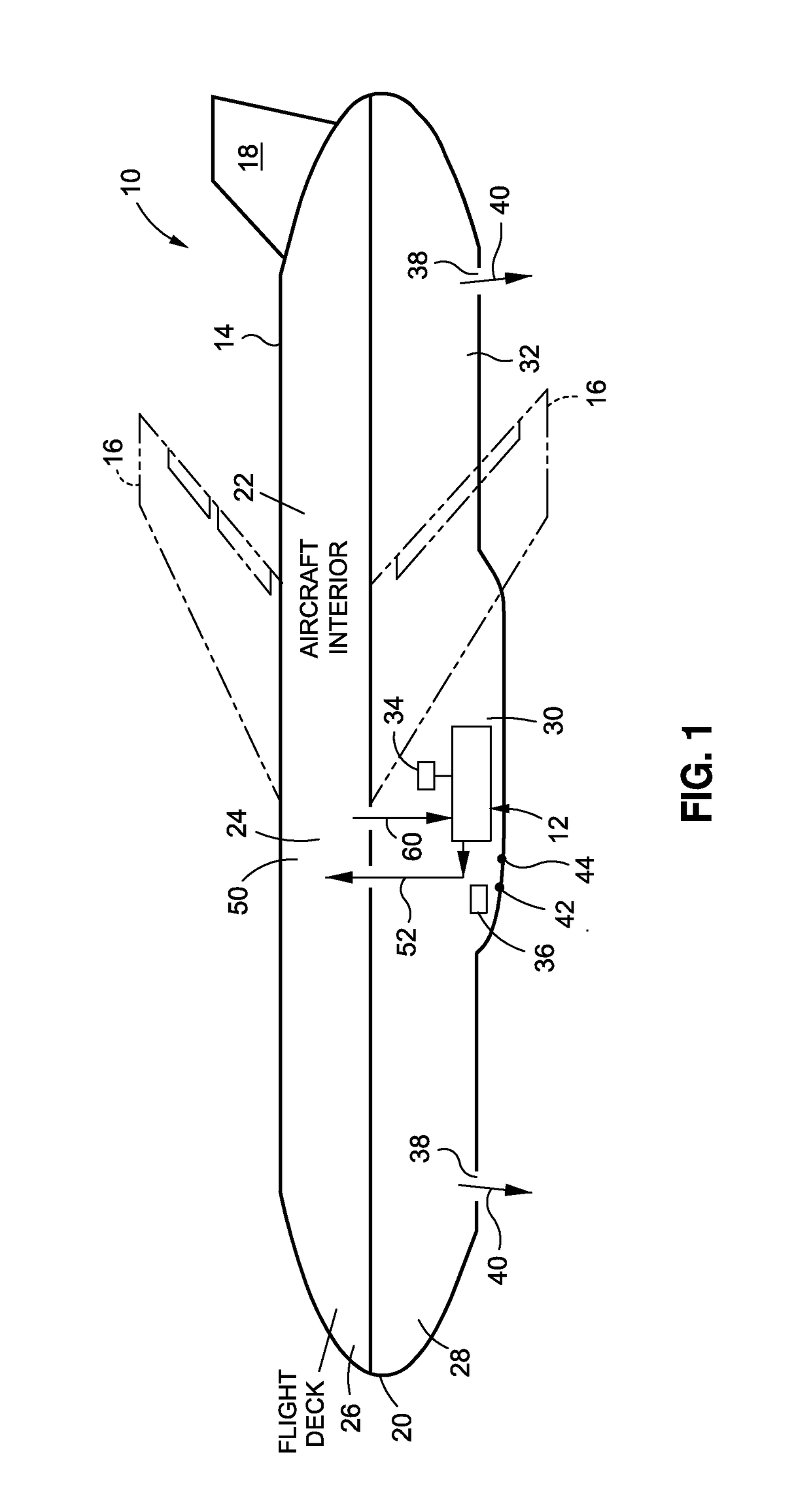
[0030]Now referring to the Figures, FIG. 1 is an illustration of a schematic diagram of an aircraft 10 having one of the embodiments of an aircraft air conditioning system 12 of the disclosure. As shown in FIG. 1, the aircraft 10 may comprise a fuselage 14, a pair of wings 16, a tail 18, and a nose 20. The fuselage 14 defines an aircraft interior 22 (see FIG. 1). As further shown in FIG. 1, the aircraft interior 22 may comprise an aircraft cabin 24 preferably for passengers or cargo, a flight deck 26 prefe...


PUM


Abstract

There are provided aircraft air conditioning systems and methods. The aircraft air conditioning system has a duct in an aircraft connected to an aircraft cabin and configured to flow pressurized cabin outflow air from the aircraft cabin. The aircraft air conditioning system further has a turbine connected to the duct and configured to reduce a temperature of the pressurized cabin outflow air and to generate power, and further has a compressor configured to generate a compressed inlet air stream, and further has an air conditioning pack configured to receive a reduced temperature cabin outflow air from the turbine and configured to receive the compressed inlet air stream from the compressor. The air conditioning pack has a cooling cycle system, a humidity control system, and one or more heat exchangers configured to use the reduced temperature cabin outflow air as a heat sink.

Description

BACKGROUND[0001]1) Field of the Disclosure[0002]The disclosure relates generally to air conditioning systems and methods, and more particularly, to air conditioning systems and methods for pressurized aircraft that provide increased air conditioning system efficiency through reduction in power usage, as well as expanded air conditioning system capability at high aircraft speeds.[0003]2) Description of Related Art[0004]A primary function of aircraft air conditioning and thermal management systems is to transfer heat away from aircraft equipment, aircraft occupants, and aircraft interior compartments, such as the passenger cabin, cargo holds, and other interior compartments. In removing such heat, the aircraft air conditioning and thermal management systems typically require a heat sink to transfer the heat energy to. Possible heat sinks offering the capacity commensurate to the aircraft air conditioning and thermal management system's need may include ram air, aircraft surfaces (e.g....

Claims


Application Information

Patent Timeline
Patent Type & Authority Patents(United States)
IPC IPC(8): B64D13/02B64D13/06
CPCB64D13/06B64D2013/0648B64D2013/0662B64D2013/0618B64D2013/0674Y02T50/40Y02T50/50
Inventor FITERMAN, CHARLES J.ATKEY, WARREN A.
Owner THE BOEING CO
Why Eureka
Try Eureka