Jet engine attachment device

a technology for jet engines and attachment devices, which is applied in the direction of efficient propulsion technologies, machines/engines, mechanical apparatuses, etc., can solve the problems of unburned fuel, inefficient fuel, and excessive use of afterburners, so as to reduce the temperature and volume of sound produced by the engine, increase the thrust and fuel efficiency, and reduce the effect of engine temperature and volum

Active Publication Date: 2017-06-06
WRC JET INNOVATIONS LP
View PDF17 Cites 8 Cited by
  • Summary
  • Abstract
  • Description
  • Claims
  • Application Information

AI Technical Summary

Benefits of technology

[0008]The principles and embodiments of the present invention relate to a device designed for integration with the exhaust pipe of a jet engine, wherein the device may be a separate component designed to attach to an existing jet engine exhaust pipe, or it may be an integral component of the exhau

Problems solved by technology

As recognized by those skilled in the art of jet and rocket engine design, the use of afterburners requires a tremendous amount of additional fuel.
This can increase thrust, but is very fuel inefficient, as the afterburner does not bum the fuel as efficiently as does the combustion section of a jet engine.
A typical afterburner operates with exhaust gas that has limited oxygen content, which is insufficient for the complete combustion of the injected fuel, so some of the fuel is left unburned as it exits the afterburner.
Since the air has been used for

Method used


Image

  • Jet engine attachment device
  • Jet engine attachment device
  • Jet engine attachment device

Examples


Embodiment Construction

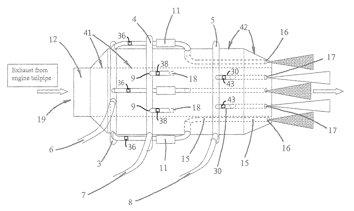
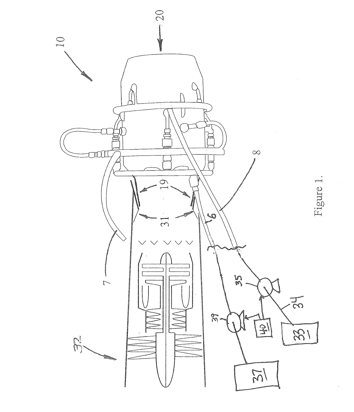
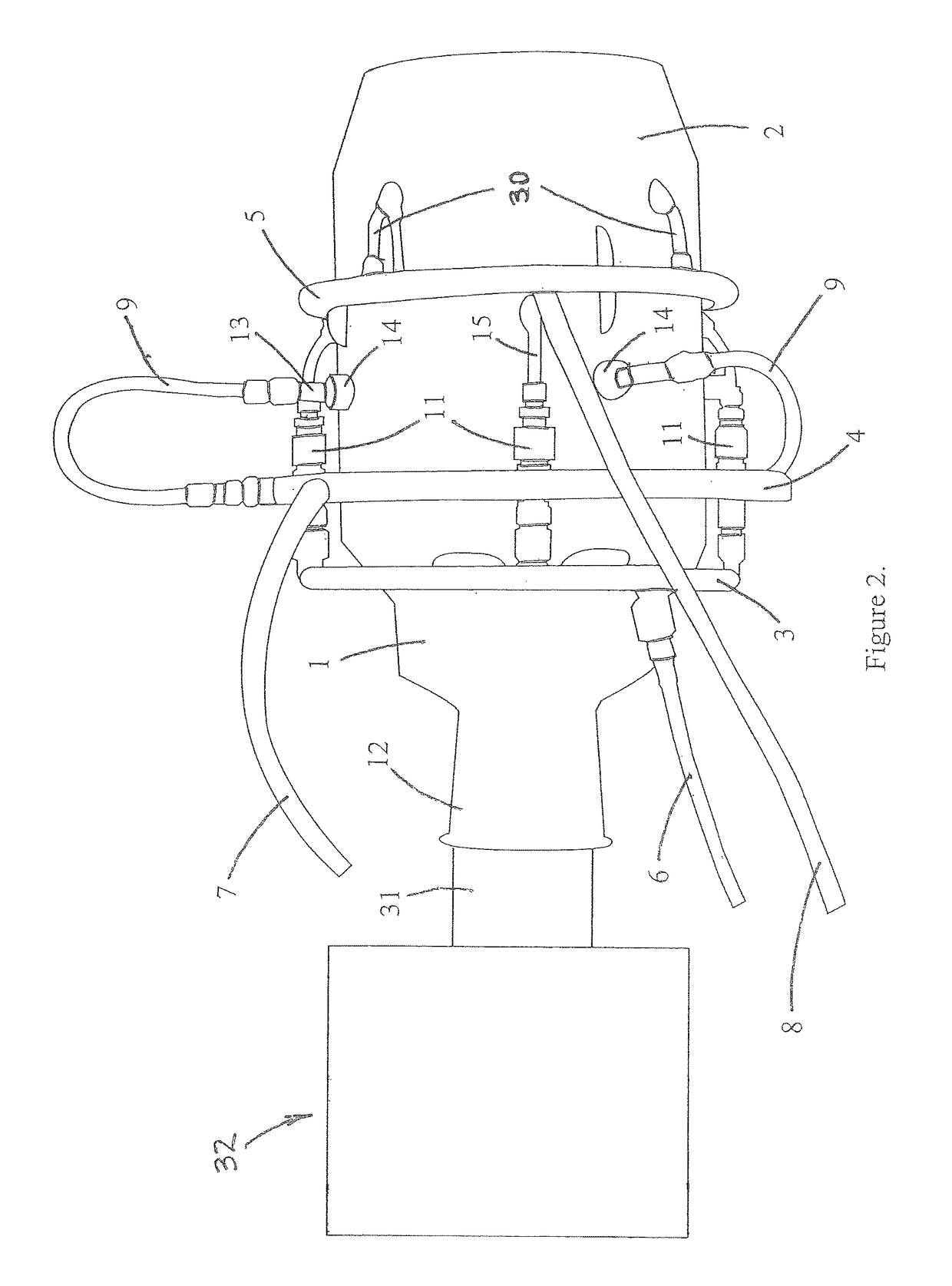
[0035]The principles and embodiments of the present invention relate to systems and devices designed for attachment to the exhaust pipe of a jet engine to improve thrust, reduce the thermal signature, and reduce the noise level of a jet engine. Embodiments of the present invention, for example, may be a separate component designed to attach to an existing jet engine exhaust pipe, or it may be an integral component of the exhaust pipe installed during the manufacture of the engine assembly. The embodiments of the present invention are also directed to methods of improving the thrust and reducing the thermal signature and noise level of jet engines employing the embodiments of the various systems and devices.

[0036]Principles and embodiments of the invention also relate to injecting various materials into a jet engine to lower the temperature of the exhaust gases, increase the efficiency of the fuel combustion, and / or reduce the sound levels generated by the exhaust gases.

[0037]Princip...


PUM


Abstract

The principles and embodiments of the present invention relate to a device designed for integration with the exhaust pipe of a jet engine, wherein the device may be a separate component designed to attach to an existing jet engine exhaust pipe, or it may be an integral component of the exhaust pipe installed during the manufacture of the engine assembly. In an embodiment of the invention, the device supplies both a cooling liquid and an oxygen supply to the jet engine to increase its thrust and fuel efficiency, and reduce the temperature and the volume of sound produced by the engine.

Description

FIELD OF THE INVENTION[0001]The principles of the present invention relates to systems and methods of reducing temperature signatures, reducing noise levels, and increasing the fuel efficiency of jet engine exhaust.BACKGROUND OF THE INVENTION[0002]A jet engine produces a fast moving exhaust to produce thrust. Typically, a compressor pulls ambient air into a combustion chamber where it is mixed with a fuel to generate a hot exhaust gas. This exhaust gas then exits the engine and by Newton's law of equal and opposite reaction produces a forward thrust. A turbine element in the path of the exhaust then is spun by the exhaust gas. The turbine is connected by a shaft to the compressor, thereby allowing more air to be drawn into the engine in a Brayton cycle combustion process. Engine thrust depends upon exhaust gas velocity and mass flow rate of gas.[0003]Jet engines contain afterburners which give the jet additional thrust. In some operating modes, such as take-off, supersonic flight, a...

Claims


Application Information

Patent Timeline
IPC IPC(8): F02C1/00F02C7/141F02C7/16F02K1/82
CPCF02C7/141F02C7/16F02K1/822F05D2220/323F05D2270/051F02C7/222F02K3/10Y02T50/60
Inventor WILKINS, JR., JOE SAMPLATT, DONALD WALTERRANKIN, JONATHAN L.
Owner WRC JET INNOVATIONS LP
Why Eureka
Try Eureka