Plated terminal for connector and terminal pair

a technology of plated terminals and connectors, applied in the direction of coupling contact members, etc., can solve the problems of high friction coefficient, difficult connection operation, and large insertion force, and achieve the effect of suppressing the insertion force of the terminal, reducing the friction coefficient of the surface, and high hardness

Active Publication Date: 2017-06-06
AUTONETWORKS TECH LTD +2
View PDF12 Cites 2 Cited by
  • Summary
  • Abstract
  • Description
  • Claims
  • Application Information

AI Technical Summary

Benefits of technology

[0021]The plating layer of the above-described terminal for connector is unlikely to be dug up or adhere to itself at a connector contact since the tin-palladium alloy containing layer having high hardness is formed on the surface of the base material. This reduces a friction coefficient of the surface and suppresses a terminal insertion force.
[0022]The friction coefficient is reduced more effectively if the composition, structure, dynamic friction coefficient and hardness of the alloy containing layer are specified as described above. Particularly, since the first metal phase made of the alloy of tin and palladium has a high effect in reducing the friction coefficient, the friction coefficient of the connector contact portion is effectively reduced by setting the exposed surface ratio of the first metal phase on the surface of alloy containing layer at 10% or higher.
[0023]On the other hand, since the second metal phase made of pure tin or the alloy having a higher ratio of tin to palladium than in the first metal phase has low contact resistance, it is possible to suppress contact resistance of the connector contact portion and establish good electrical contact by setting the exposed surface ratio of the first metal phase on the surface of the alloy containing layer at 80% or lower. This can combine a reduction of the friction coefficient and the ensuring of connection reliability. The glossiness of the surface measurable by a simple method and having a good correlation to the exposed surface ratio of the first metal phase may be used as an index for obtaining such a connector terminal capable of combining a low friction coefficient and high connection reliability.
[0024]If a domain of the first metal phase having a shorter dimension than the longest one of straight lines crossing the contact portion to be brought into electrical contact with another electrically conductive member is exposed on the surface of the contact portion, both the first metal phase and the second metal phase are exposed in the contact portion. Thus, an effect of reducing the friction coefficient by the first metal phase and an effect of reducing contact resistance by the second metal phase can be simultaneously enjoyed. Particularly, if the contact portion is in the form of an emboss instead of in the form of a flat plate, further if a radium of that emboss is not smaller than 3 mm, the effect of reducing the friction coefficient is increased.
[0025]According to the terminal pair of the above invention, a force necessary to insert the terminal is suppressed since the tin-palladium alloy containing layer having high hardness is formed on the surface of either one of the male and female connector terminals to reduce the friction coefficient of the surface.
[0026]If a contact load applied to the contact portion where the male and female connector terminals come into contact with each other is not lower than 2 N, an oxide film formed on the surface of the second metal phase can be broken to establish electrical conduction between the both terminals. Thus, a good electrical connection property of the second metal phase can be effectively utilized. Further, if the contact load is not lower than 5 N, the effect of reducing the friction coefficient is greatly increased.

Problems solved by technology

However, since the tin oxide film is destroyed with a weak force and the soft tin layer is easily exposed, good electrical contact is established.
In the connector terminal formed with the tin plating layer, good electrical contact can be established as described above due to the softness of tin, whereas there is a problem of a high friction coefficient at the time of terminal connection likewise due to the softness of tin.
Particularly, in the case of using tin plating for terminals of a multi-pole fitting connector including many terminals, the insertion force becomes larger as the number of the terminals increases and a connecting operation becomes difficult.

Method used


Image

  • Plated terminal for connector and terminal pair
  • Plated terminal for connector and terminal pair
  • Plated terminal for connector and terminal pair

Examples


Embodiment Construction

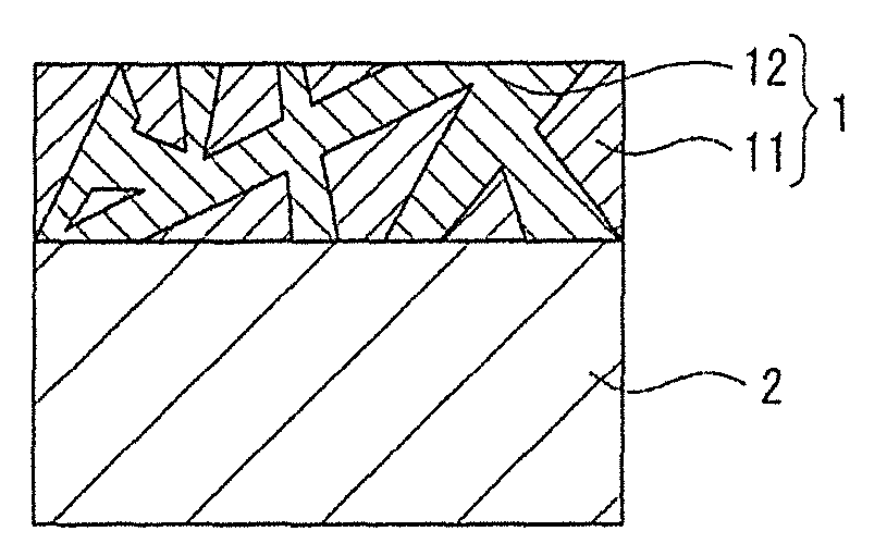
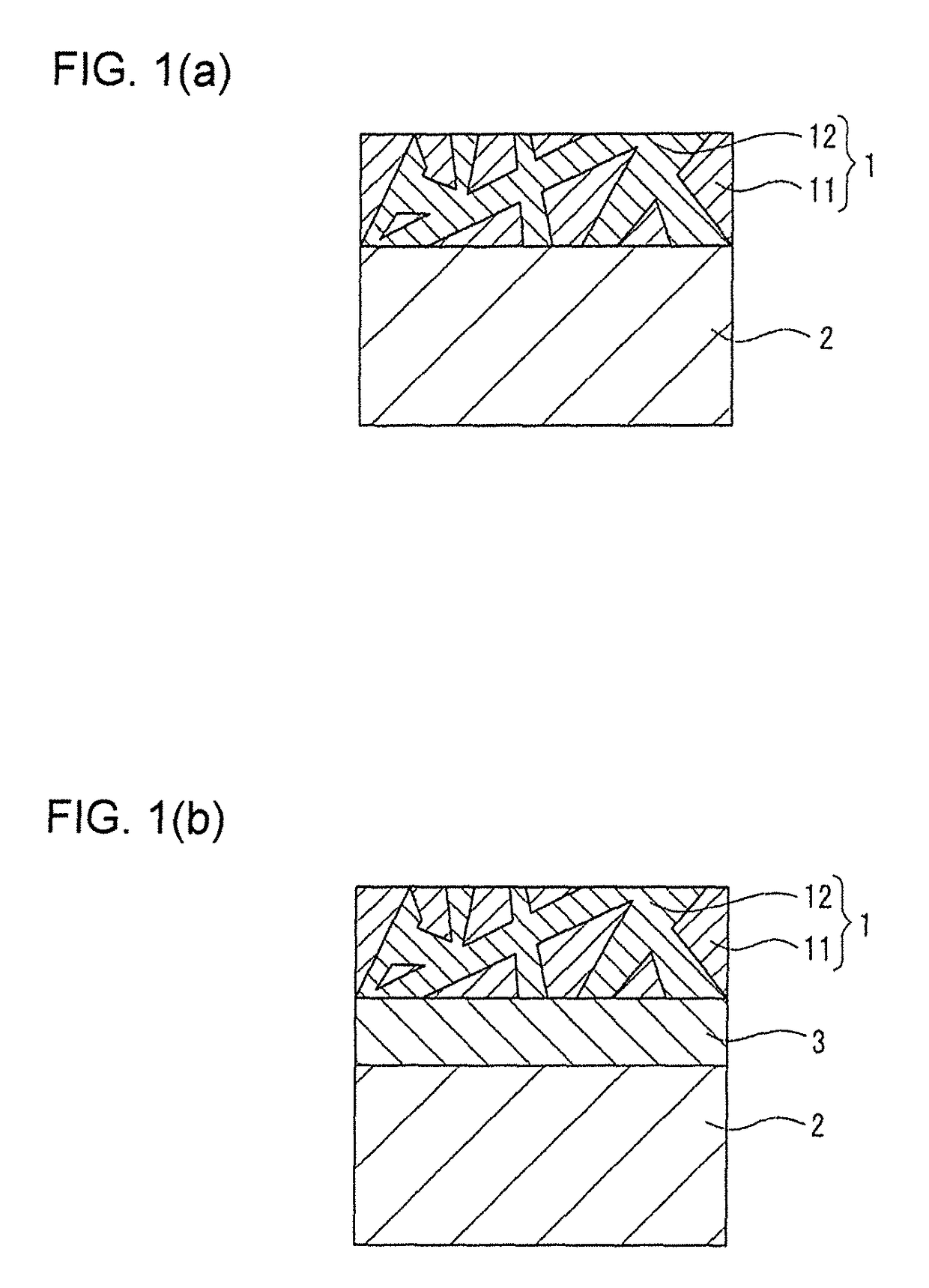
[0034]A plated terminal for connector according to the present invention (hereinafter, may be merely referred to as a plated terminal or a connector terminal) is such that a tin-palladium alloy containing layer 1 (hereinafter, may be merely referred to as an alloy containing layer) is formed on a surface of a base material 2 as shown in a cross-sectional configuration in FIG. 1. The alloy containing layer 1 is formed at least on a part of the connector terminal for connector to be brought into contact with a mating terminal.

[0035]The base material 2 is a base material of the connector terminal and made of copper or copper alloy. The tin-palladium alloy containing layer 1 may be directly formed on the base material 2 as shown in FIG. 1(a) or may be formed after an under plating layer 3 made of nickel or nickel alloy is formed on the surface of the base material 2 as shown in FIG. 1(b). The under plating layer 3 has an effect of suppressing the diffusion of copper atoms from the base ...


PUM

PropertyMeasurementUnit
thicknessaaaaaaaaaa
radiusaaaaaaaaaa
dynamic friction coefficientaaaaaaaaaa

Abstract

The present invention aims to provide a plated terminal for connector which requires a smaller insertion force by reducing a friction coefficient and a terminal pair formed using such a plated terminal for connector. An alloy containing layer (1) made of tin and palladium and containing a tin-palladium alloy is formed on a surface of a terminal base material (2) made of copper or copper alloy. Here, the alloy containing layer (1) is preferably such that domain structures of a first metal phase (11) made of an alloy of tin and palladium are formed in a second metal phase (12) made of pure tin or an alloy having a higher ratio of tin to palladium than in the first metal phase (11).

Description

BACKGROUND OF THE INVENTION[0001]1. Field of the Invention[0002]The present invention relates to a plated terminal for connector, more particularly to a plated terminal for connector including an alloy plating layer, and a terminal pair formed by using such a plated terminal.[0003]2. Description of the Related Art[0004]Copper and copper alloy having high electrical conductivity, good ductility and appropriate strength are used for electrically conductive members used such as in electrical connection terminals. Since insulating films such as oxide films and sulfide films are formed on surfaces of these, contact resistance is high at the time of contact with other conductors. Accordingly, a terminal formed by applying tin plating 21 to a surface of a base material 22 such as copper or copper alloy as shown in FIG. 7(b) has been conventionally generally used as a connector terminal for connecting an electrical component or the like of an automotive vehicle. For example, a connector ter...

Claims


Application Information

Patent Timeline
Patent Type & Authority Patents(United States)
IPC IPC(8): H01R13/03C25D7/00C25D3/60C25D5/12
CPCH01R13/03C25D7/00C25D3/60C25D5/12C25D5/627
Inventor SAKA, YOSHIFUMIWATANABE, HAJIMESATOU, MIKIOOOKUBO, MASAYUKI
Owner AUTONETWORKS TECH LTD
Why Eureka
Try Eureka