Illuminating balloon catheter and method for using the catheter

a technology of illuminating balloons and catheters, which is applied in the field of catheters, can solve the problems of less-skilled technicians, less-skilled health care personnel, and aging of a large percentage of the population, and achieve the effect of quick and rapid deflating

Active Publication Date: 2017-06-13
MAYSER
View PDF60 Cites 0 Cited by
  • Summary
  • Abstract
  • Description
  • Claims
  • Application Information

AI Technical Summary

Benefits of technology

[0031]It is accordingly an object of the present invention to provide a pressure-limiting balloon catheter and method for using the catheter that overcome the hereinafore-mentioned disadvantages of the heretofore-known devices and methods of this general type and that does not inflate past the tearing limit of a lumen in which the catheter is placed, for example, in the urethra, and quickly and rapidly deflates if pulled out prior to deflation of the balloon.
[0032]The purpose of the breakaway catheter of the present invention is to prevent injury by having the balloon automatically deflate before an injury can occur. While the catheter of the present invention makes it a safer device for urinary drainage, the present invention can also be used for any procedures in which balloons are used to dilate cavities. Examples of these procedures include coronary artery vessels, peripheral vascular vessels, such as the aorta and extremity vessels. Balloon dilations of other lumens, such as ureters and the esophagus, are also candidates for use of the catheter of the present invention.

Problems solved by technology

First, a greater percentage of the population is aging.
Second, there is a current trend to use less-skilled health care personnel to perform more procedures and to be responsible for treatment, both of which save money.
This leaves only the less-skilled technicians with the task of inserting catheters and taking vital signs.
Under such circumstances, more injuries are likely.
Lastly, catheter-related complications are becoming more severe due to the increased use of anticoagulation medication, such as Plavix™, that is frequently prescribed in treating cardiovascular disease.
Yet another possible complication arising from the standard Foley catheter is that the balloon will not deflate even when the deflation mechanism is activated.
This situation can occur, for example, because the wrong fluid is used to inflate the balloon, such as saline, which can crystallize.
Sometimes, the ability to deflate the catheter is interrupted because the drainage channel that is used to deflate the balloon becomes obstructed, which is common if the catheter is left in place too long.

Method used


Image

  • Illuminating balloon catheter and method for using the catheter
  • Illuminating balloon catheter and method for using the catheter
  • Illuminating balloon catheter and method for using the catheter

Examples


first embodiment

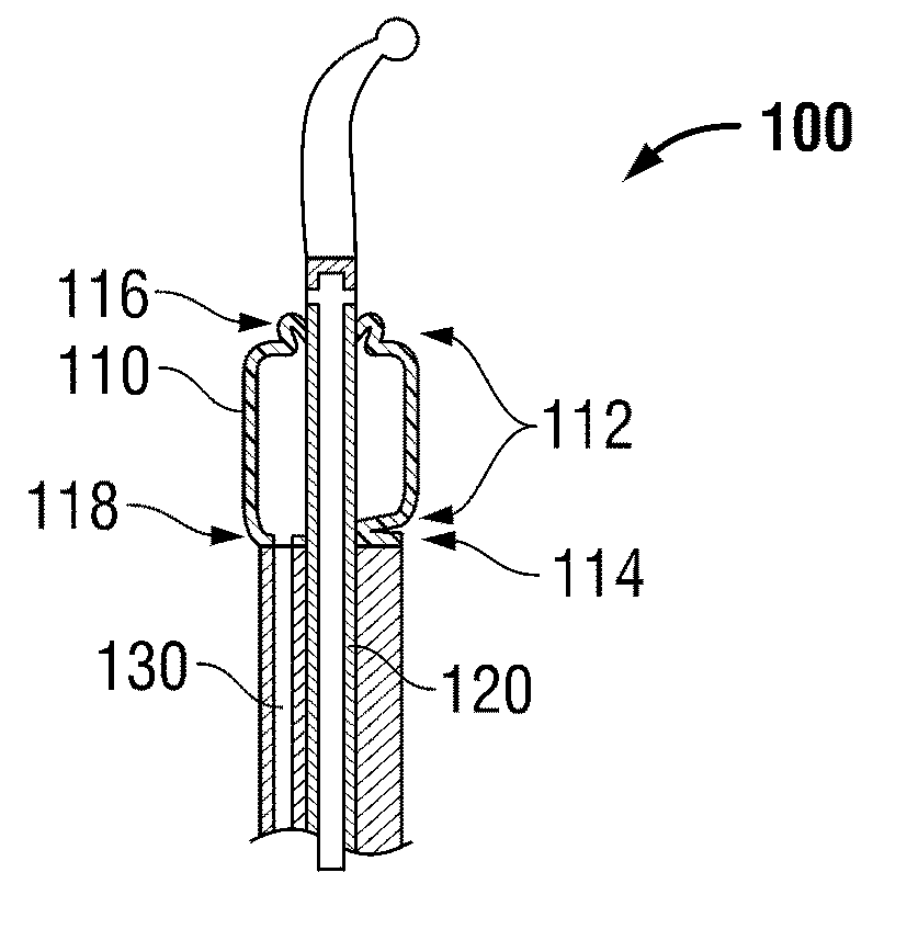
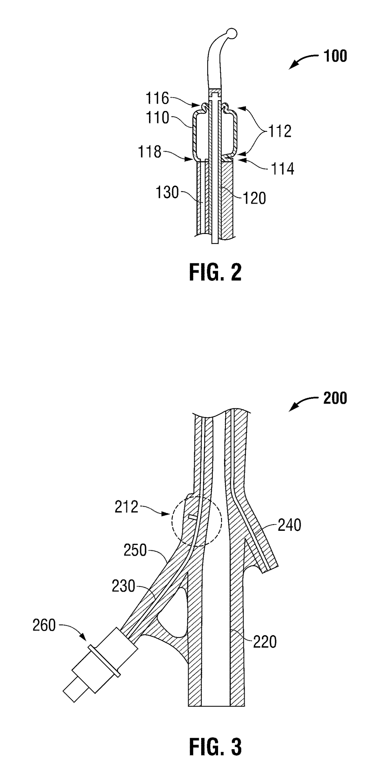
[0154]Referring now to the figures of the drawings in detail and first, particularly to FIG. 2 thereof, there is shown a pressure-limiting balloon catheter 100 that does not inflate past the tearing limit of a lumen in which the catheter 100 is placed, for example, in the urethra.

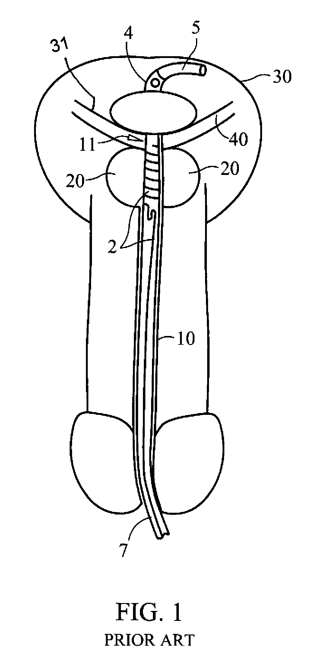
[0155]To prevent occurrences of urethra tearing due to premature-improper inflation of the balloon and / or due to premature removal of an inflated balloon, the invention of the instant application provides the balloon 110 with a balloon safety valve 112. As set forth above, in a balloon 3 of a conventional catheter (see reference numerals 1 to 5 in FIG. 1), the balloon 3 is fixed to the outer surface of the fluid drainage line 120 (not shown in FIG. 1) and is not intended to be removed therefrom or to burst thereon unless an extraordinary amount of inflation occurs. Such a tearing event is not supposed to occur under any circumstances during use with a patient. If such an event happens, the material of the b...

second embodiment

[0161]the one-use breaking safety valve of a pressure-limiting balloon catheter 200 is shown in FIG. 3. The catheter 200 has a fluid drainage line 220, a balloon inflation lumen 230, and a secondary lumen 240.

[0162]The fluid drainage line 220 is connected fluidically to the body cavity (i.e., the bladder 30) for draining fluid from the body cavity.

[0163]The secondary lumen 240 can be used for any purpose, for example, for housing the radiation line that will supply energy to the radiation coil 2. It can also be used for injecting fluid into any distal part of the catheter 200 or even the body cavity itself.

[0164]The balloon inflation lumen 230 begins at a proximal end with an inflating connector 260 that, in a preferred embodiment, is a female luer connector (of course, it can be a male luer connector too). The balloon inflation lumen 230 continues through the body of the catheter 200 all the way to the balloon and is fluidically connected to the interior of the balloon.

[0165]The ba...

fifth embodiment

[0191]FIG. 17 illustrates a fifth alternative embodiment of the illuminating balloon catheter 100. Specifically, the illuminating device 200 is tubular and is led through the fluid drainage lumen 120 in a longitudinally movable manner. The illuminating device 200 has a distal-most portion at which is disposed an illuminator 206a. The illuminator 206a can be formed from an unshielded portion of a fiber optic or can be an LED having an illumination direction disposed along a radial line orthogonal to the longitudinal extent of the illuminating device 200. Because the illuminating device 200 can be rotated 360 degrees inside the fluid drainage lumen 120, a portion of the drainage assembly 150 inside the balloon is transparent. Thus, as the illuminator 206a is rotated within the fluid drainage lumen 120, the light beam also rotated within the balloon. In this embodiment, therefore, the catheter need not be rotated inside the patient's urethra. To make sure that a majority of the illumin...


PUM


Abstract

To perform pelvic surgery, a directionally illuminating balloon catheter enters a bladder. The catheter has a multi-lumen shaft. The balloon defines an interior fluidically connected to a balloon inflation lumen and is inflated therethrough. The balloon comprises a light source, a light-radiating surface adjacent the shaft-balloon junction, and a substantially opaque surface disposed at a portion of the balloon other than the light-radiating surface such that the integrated light source illuminates a distal half of the environment outside the balloon. The balloon is inflated while in the bladder. Light from the light source is directed out through the light-radiating surface to illuminate at least a portion of a procedure area opposite the bladder-prostate junction. With the light illuminating the portion of the procedure area, at least a portion of a pelvic surgery is performed at the portion of the procedure area.

Description

CROSS-REFERENCE TO RELATED APPLICATIONS[0001]This application:[0002]claims the priority, under 35 U.S.C. §119, of U.S. Provisional Patent Application No. 62 / 013,598, filed Jun. 18, 2014;[0003]is a continuation-in-part application of U.S. patent application Ser. No. 11 / 339,258, filed Jan. 25, 2006, and now U.S. Pat. No. 7,883,503 (which application claims the benefit under 35 U.S.C. §119(e) of U.S. Provisional Patent Application Nos. 60 / 647,204 and 60 / 647,205, filed Jan. 26, 2005);[0004]is a continuation-in-part application of U.S. patent application Ser. No. 12 / 972,619, filed Dec. 20, 2010, and now U.S. Pat. No. 8,439,895; and[0005]is a continuation-in-part application of U.S. patent application Ser. No. 13 / 649,150, filed Oct. 11, 2012, and now U.S. Pat. No. 8,801,699,the prior applications are hereby incorporated herein by reference in their entireties.BACKGROUND OF THE INVENTION[0006]Field of the Invention[0007]The present invention relates to a catheter, especially a flexible ill...

Claims


Application Information

Patent Timeline
Patent Type & Authority Patents(United States)
IPC IPC(8): A61M27/00A61F13/00A61B1/06A61F2/00A61M29/00A61M25/10A61M25/00
CPCA61B1/06A61M25/10A61M25/0017A61M2025/1093
Inventor KALSER, GARYMAYBACK, GREGORY L.
Owner MAYSER
Why Eureka
Try Eureka