Chemical clean for membrane filter

a filter and membrane technology, applied in the field of cleaning methods, can solve the problems of deterioration of filter permeability, and increased transmembrane pressure and ultimately filtration energy consumption

Active Publication Date: 2017-06-13
EVOQUA WATER TECH LLC
View PDF1099 Cites 3 Cited by
  • Summary
  • Abstract
  • Description
  • Claims
  • Application Information

AI Technical Summary

Benefits of technology

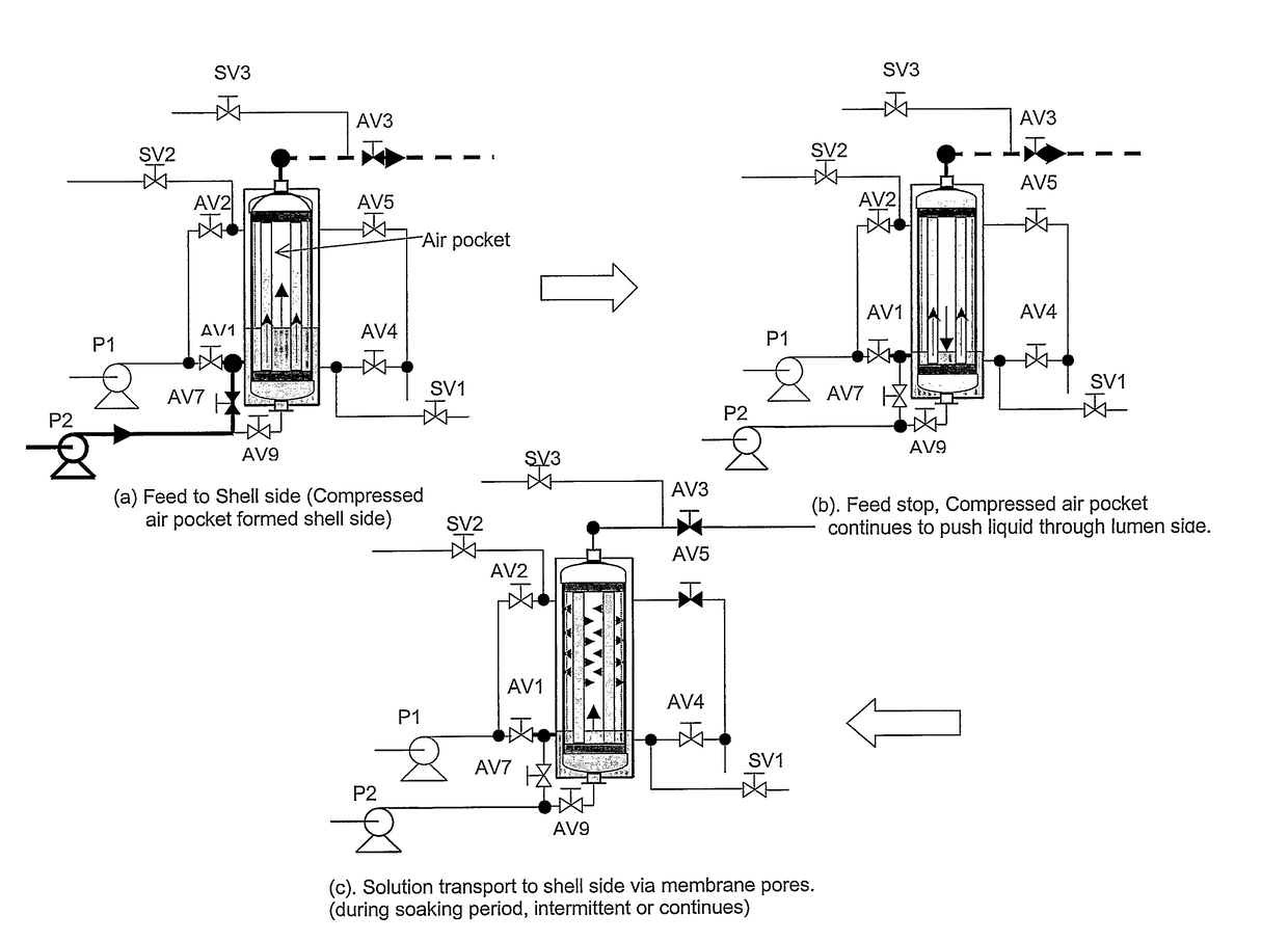
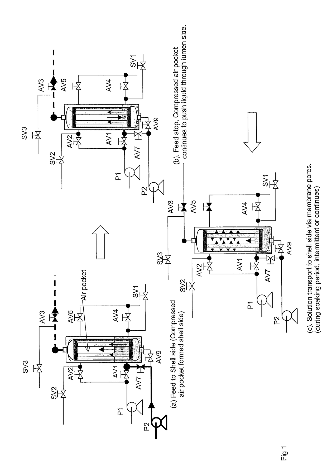
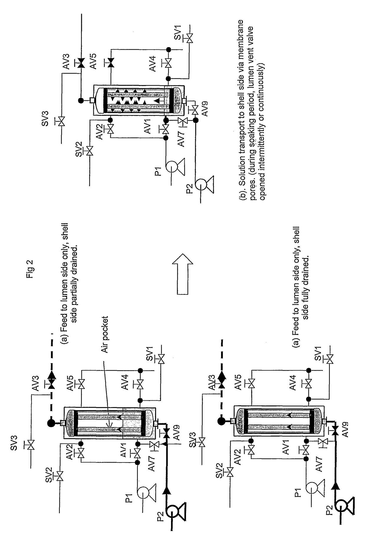
[0021]allowing the cleaning agent to contact the permeate side of the membrane for a predetermined time to contact the pores of the membrane and diffuse into the feed side fluid.
[0034]The cleaning solution can be any conventional cleaning solution, either acidic, basic or neutral, or can be oxidative or reductive depending upon the origin of the foulant. The cleaning agent can also inorganic or organic. Preferred cleaning agents include dissolved halogens, such as chlorine, or dissolved oxidative or reductive agents, for example sulfite based reagents. Alternatively, cleaning agents may be chelating agents, such as citric acid or EDTA. To facilitate the wetting out and dissolving the foulant, a small amount of surfactant may be added to the cleaning solution.
[0035]In a membrane system, the preference on delivery of chemical cleaner varies according to the system design. For example, in some membrane filtration systems it is preferable that chemical cleaner be delivered to the feed side of the membrane. If so, the requirement on the water used to prepare the chemical solution in terms of solid content is not particularly stringent and the cleaning solution may be re-used for several times. This, however, may require a chemical storage tank and a chemical transfer pump. This delivery method is commonly found in large membrane systems. In other membrane systems, it is preferable to deliver the chemical cleaner to the permeate side to further reduce the volume of chemical solution and improve ease of operation. A dosing pump may be used in such circumstances. The methods of the present invention are adapted to handle either feed side or lumen side dosing.

Problems solved by technology

The presence of a fouling layer or plugged pores or both can significantly increase the transmembrane pressure and ultimately the filtration energy consumption.
Frequent backwashes with either filtrate or gas can partially reclaim the membrane permeability, however, with these methods it is known that foulants may continue to build up on the membrane surface and in the pores.
Successive backwashes do not remove all the deposited material, and consequently over time there is deterioration in filter permeability.
This is a common method currently used for full chemical recovery of membrane performance, however it suffers from the drawback that a significant volume of chemical solution is required and the process generates large volumes of chemical waste.

Method used


Image

  • Chemical clean for membrane filter
  • Chemical clean for membrane filter
  • Chemical clean for membrane filter

Examples


example

[0082]A six-module Memcor CMF-L pilot was used for the comparative tests. The filtration process involves 30 minutes filtration followed by a gas pushed backwash. The recycle repeats several times before maintenance clean is carried out.

[0083]As shown in FIG. 4, the membrane fouling rate is judged by an increase in the membrane resistance. After filtering for 30 minutes, the membrane resistance rises. The backwash can partially reduce the membrane resistance. However, the backwash did not fully recover the membrane's permeability and the trend of resistance continues to rise. Maintenance clean was performed to further reduce the membrane's resistance and therefore better recover the membrane's permeability. A general trend is depicted in FIG. 4. The efficiency of maintenance clean is defined as:

MC Efficiency=(R1-R2) / (R1-R0)[0084]Where R0 is Resistance straight after the last chemical clean[0085]R1 is Resistance straight after the last backwash before maintenance clean[0086]R2 is Res...


PUM

PropertyMeasurementUnit
timeaaaaaaaaaa
timeaaaaaaaaaa
timeaaaaaaaaaa

Abstract

A method of cleaning a porous polymeric membrane having a feed side and a permeate side including the steps of introducing a fluid containing a cleaning agent to the permeate side of a membrane allowing the cleaning agent to contact the permeate side of the membrane for a predetermined time, and contact the pores of the membrane, or introducing a fluid containing a cleaning agent to the feed side of a membrane; applying a transmembrane pressure to force the fluid containing the cleaning agent from the feed side to the permeate side of the membrane; allowing the cleaning agent to contact the permeate side of the membrane for a predetermined time, and contact the pores of the membrane. Preferably a concentration gradient between the feed side fluid and the lumen side fluid containing the cleaning agent causes cleaning agent to diffuse into the feed side fluid. Pressure may be applied to the fluid containing a cleaning agent to dislodge, where present, dissolved and undissolved solid from the membrane pores. The pressure may be applied in a pulsed fashion, and can be by way of compressed air at a pressure not more than the membrane's bubble point. The methods of the present invention may be preceded by, or followed with a backwash.

Description

CROSS REFERENCE TO RELATED APPLICATIONS[0001]This application is a U.S. national stage application and claims the benefit under 35 U.S.C. §371 of International Application No. PCT / AU2006 / 000552 filed on Apr. 28, 2006, entitled CHEMICAL CLEAN FOR MEMBRANE FILTER, which is based on Australian Patent Application No. 2005902169 filed on Apr. 29, 2005, entitled MAINTENANCE CLEAN FOR MEMBRANE FILTER, each of which is entirely incorporated herein by reference for all purposes, and to which this application claims the benefit of priority.FIELD OF THE INVENTION[0002]The invention relates to methods of cleaning suitable for use in filtration apparatus. More particularly, the invention relates to methods of cleaning microfiltration or ultrafiltration membranes used for water filtration purposes.BACKGROUND ART[0003]Microfiltration and ultrafiltration membrane filters are increasingly used in municipal drinking water treatment and wastewater treatment. With a typical microfiltration or ultrafilt...

Claims


Application Information

Patent Timeline
Patent Type & Authority Patents(United States)
IPC IPC(8): C02F1/44B01D65/02B01D61/22
CPCB01D65/02B01D61/22B01D2321/04B01D2321/16C02F1/444C02F2303/16B01D65/08
Inventor ZHA, FUFANGCAO, ZHIYI
Owner EVOQUA WATER TECH LLC
Why Eureka
Try Eureka