Catalyzed filter for treating exhaust gas

a technology of catalyst filter and exhaust gas, which is applied in the direction of physical/chemical process catalyst, machine/engine, separation process, etc., can solve the problems of higher backpressure and soot load backpressure, and achieve the effect of reducing the concentration of nox

Active Publication Date: 2017-06-27
JOHNSON MATTHEY PLC
View PDF46 Cites 7 Cited by
  • Summary
  • Abstract
  • Description
  • Claims
  • Application Information

AI Technical Summary

Benefits of technology

[0008]Applicants have surprisingly found that the backpressure across a wall-flow filter can be reduced by coating the filter from the outlet side only with a catalyst washcoat, provided that the washcoat contains catalyst particles that are large relative to the filter's mean pore size. More particularly, coating from only the outlet side of a filter with a large particle washcoat unexpectedly reduces the soot loaded backpressure across the filter compared to the same filter having an equivalent amount of the same catalyst coating applied only from the inlet side of the filter or having an equivalent amount of the same catalyst coating applied evenly from both the inlet side and outlet sides of the filter. This result is also surprising because small particle washcoats applied only to the outlet side of the same filter do not produce a comparable benefit, and in fact, result in higher backpressures.
[0011]In yet another aspect of the invention, provided is a method for reducing soot in a lean burn exhaust gas comprising the steps of (a) contacting an exhaust gas stream carrying soot and optionally containing NOx, with a diesel particulate filter described herein; (b) trapping at least a portion of the soot on and / or in the diesel particulate filter while allowing the exhaust gas to pass through the diesel particulate filter; (c) periodically and / or continuously burning the trapped soot to regenerate the filter; and optionally (d) contacting the exhaust gas with a SCR catalyst coated from the outlet side of the filter to reduce the concentration of NOx in exhaust gas.

Problems solved by technology

More particularly, coating from only the outlet side of a filter with a large particle washcoat unexpectedly reduces the soot loaded backpressure across the filter compared to the same filter having an equivalent amount of the same catalyst coating applied only from the inlet side of the filter or having an equivalent amount of the same catalyst coating applied evenly from both the inlet side and outlet sides of the filter.
This result is also surprising because small particle washcoats applied only to the outlet side of the same filter do not produce a comparable benefit, and in fact, result in higher backpressures.

Method used


Image

  • Catalyzed filter for treating exhaust gas
  • Catalyzed filter for treating exhaust gas
  • Catalyzed filter for treating exhaust gas

Examples


example 1

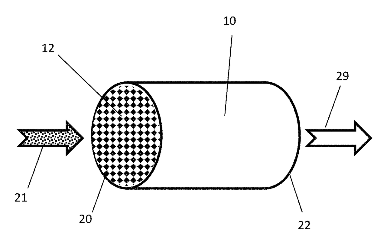
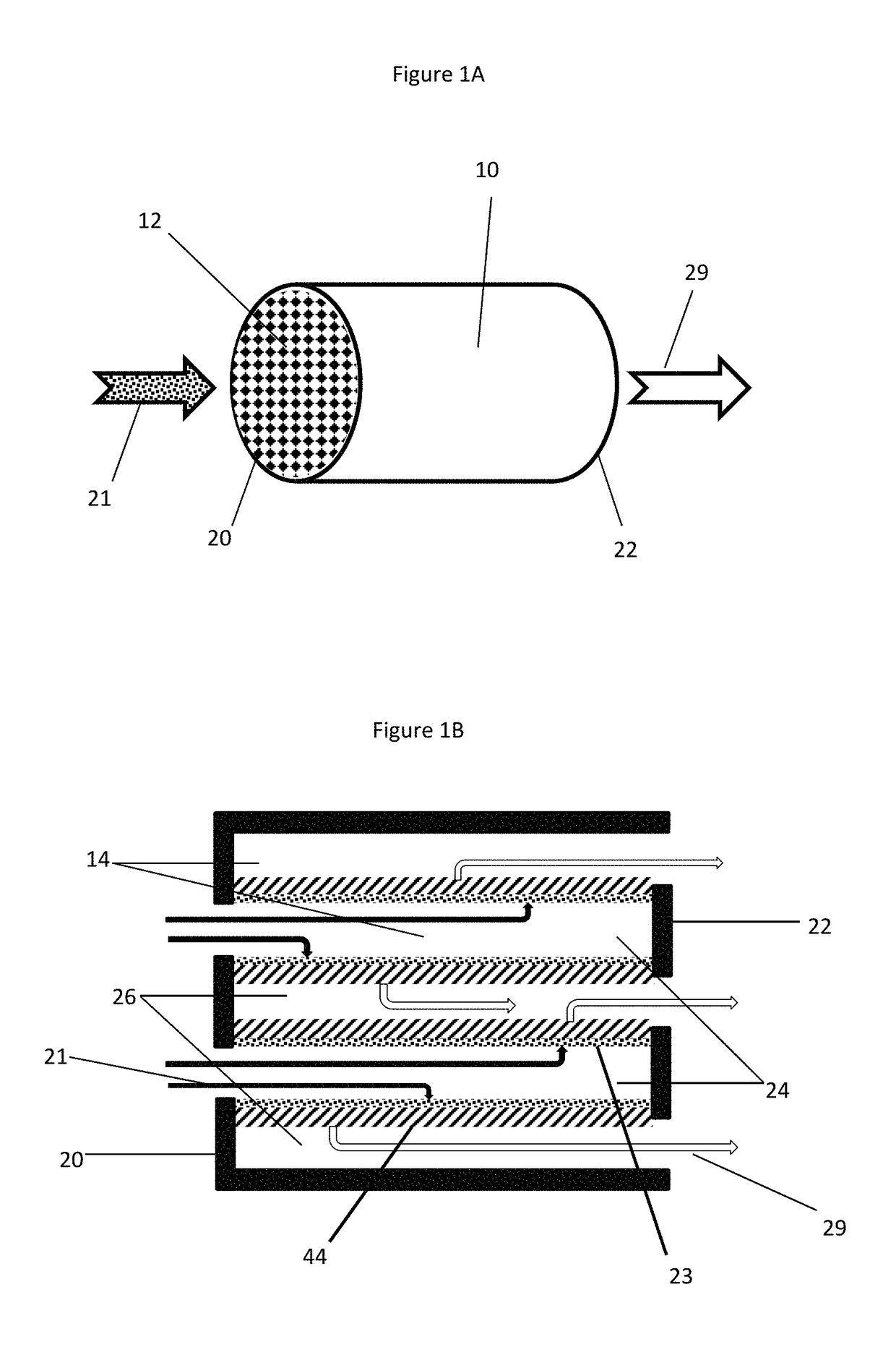
Diesel Particulate Filter with Catalyst Coated Outlet

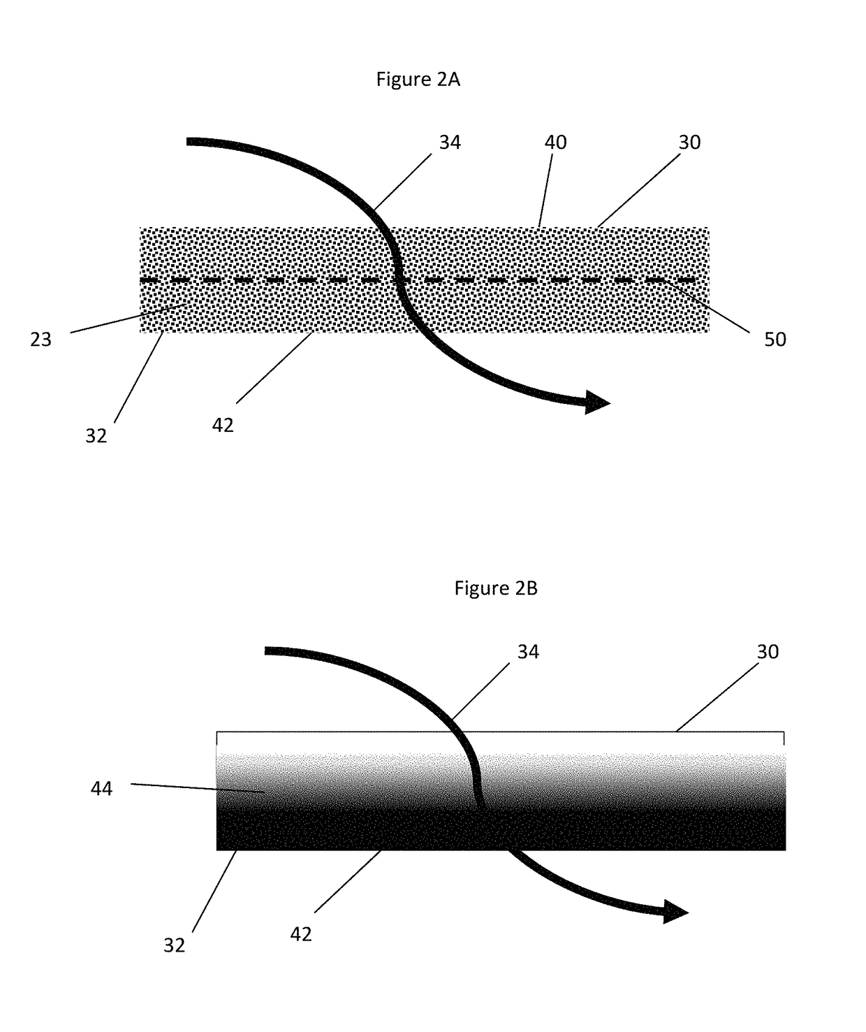
[0065]A catalytic washcoating having a copper impregnated molecular sieve having a CHA framework was washcoated from the outlet side of a honeycomb-type wall-flow filter constructed primarily of cordierite and having 300 cpsi and a wall thickness of 12 mils (0.3 mm) and then dried. Scanning Electron Microscope (SEM) imaging confirmed that the catalyst coating remained on the outlet side and interior portion of the filter wall. The inlet side of the filter wall remained free of catalyst coatings.

[0066]The washcoat was applied in an amount sufficient to form a catalyst loading of about 1 g / in3. The catalyst loading had a d50 particle size distribution of about 4.22 μm.

example 4

Comparative Backpressure Performance (Inlet vs. Outlet Coatings)

[0070]The procedures described in Examples 1-3 and Comparative Examples A-B were repeated, except that the catalyst coating was applied from the inlet side of the filter. The procedures described in Examples 1-3 and Comparative Examples A-B were again repeated, except that half of the catalyst coating was applied to the inlet side of the filter and half of the catalyst coating was applied to the outlet side of the filter. Ambient temperature air was passed through the filter at a rate of 400 cubic feet per minute (CFM). Soot was gradually introduced upstream of the filter and allowed to accumulate on the inlet side of the filter and the pressure differential across the filter (e.g., the filter's backpressure) was recorded as the soot level increased. The soot loaded back pressure (SLBP) of each filter was compared at a soot loading of about 2 to about 9 grams per cubic inch to determine which catalyst coating orientatio...


PUM

PropertyMeasurementUnit
pore sizeaaaaaaaaaa
mean pore sizeaaaaaaaaaa
porosityaaaaaaaaaa

Abstract

Provided is a diesel particulate filter capable of removing soot from an exhaust gas while operating at low backpressure, the filter comprising (a) a wall-flow filter substrate having a mean pore size, an inlet side, an outlet side, and a porous interior between the inlet and outlet sides; and (b) a catalyst composition coated from the outlet side of the substrate, wherein the catalyst composition has a d50 particle size distribution, wherein the d50 particle size distribution is greater than or equal to the mean pore size divided by 4.9, and wherein the inlet side is substantially free of a catalyst coating.

Description

BACKGROUND[0001]1. Field of Invention[0002]The present invention relates to articles for treating combustion exhaust gas. More particularly, the present invention relates to particulate filters coated with a catalyst for reducing soot and other undesirable components from lean burn combustion exhaust gas.[0003]2. Description of Related Art[0004]The largest portions of most combustion exhaust gases contain relatively benign nitrogen (N2), water vapor (H2O), and carbon dioxide (CO2); but the exhaust gas also contains in relatively small part noxious and / or toxic substances, such as carbon monoxide (CO) from incomplete combustion, hydrocarbons (HC) from un-burnt fuel, nitrogen oxides (NOx) from excessive combustion temperatures, and particulate matter (mostly soot). To mitigate the environmental impact of exhaust gas released into the atmosphere, it is desirable to eliminate or reduce the amount of these undesirable components, preferably by a process that does not generate other noxio...

Claims


Application Information

Patent Timeline
Patent Type & Authority Patents(United States)
IPC IPC(8): B01D53/94F01N3/022F01N3/035B01J35/10B01J29/03B01J29/04B01J29/072
CPCB01D53/9472F01N3/0222F01N3/035F01N2510/0682Y02T10/24Y02T10/12
Inventor CHEN, HAI-YINGDE, DEBNATHMANNING, WENDYCOX, JULIAN PETER
Owner JOHNSON MATTHEY PLC
Why Eureka
Try Eureka