

Catalyzed Filter for Treating Exhaust Gas
a filter and catalytic technology, applied in the direction of machines/engines, mechanical equipment, separation processes, etc., can solve the problems of higher backpressure and soot load backpressure, and achieve the effect of reducing the concentration of nox
Active Publication Date: 2014-12-04
JOHNSON MATTHEY PLC
View PDF40 Cites 13 Cited by
- Summary
- Abstract
- Description
- Claims
- Application Information
AI Technical Summary
Benefits of technology
The patent is about a new method for reducing soot and NOx in exhaust gas. It involves using a diesel particulate filter coated with a small particle washcoat containing catalyst particles. By coating the filter only from the inlet side and not the outlet side or evenly, the method reduces backpressure and soot loading compared to filters with the same amount of catalyst coating applied from both sides. The method also involves trapping soot on the filter and burning it periodically or continuously to regenerate the filter, and optionally using a selective catalytic reduction (SCR) catalyst to reduce NOx in exhaust gas. The technical effects of this patent are reducing soot and NOx in exhaust gas while improving the efficiency of the diesel particulate filter.
Problems solved by technology
More particularly, coating from only the inlet side of a filter with a small particle washcoat unexpectedly reduces the soot loaded backpressure across the filter compared to the same filter having an equivalent amount of the same catalyst coating applied only from the inlet side of the filter or having an equivalent amount of the same catalyst coating applied evenly from both the inlet side and outlet sides of the filter.
This result is also surprising because large particle washcoats applied only to the inlet side of the same filter do not produce a comparable benefit, and in fact, result in higher backpressures.
Method used
View moreImage
Smart ImageViewing Examples

Examples
example
Example 1: Diesel Particulate Filter with Catalyst Coated Inlet
[0066]A catalytic washcoating having a copper impregnated molecular sieve having a CHA framework was washcoated from the inlet side of a honeycomb-type wall-flow filter constructed primarily of cordierite and having 300 cpsi and a wall thickness of 12 mils (0.3 mm) and then dried. Scanning Electron Microscope (SEM) imaging confirmed that the catalyst coating remained on the inlet side and interior portion of the filter wall. The inlet side of the filter wall remained free of catalyst coatings.
[0067]The washcoat was applied in an amount sufficient to form a catalyst loading of about 1 g / in3. The catalyst loading had a d50 particle size distribution of about 1.5 μm.
Login to View More PUM
| Property | Measurement | Unit |
|---|---|---|
| mean pore size | aaaaa | aaaaa |
| mean pore size | aaaaa | aaaaa |
| porosity | aaaaa | aaaaa |
Abstract
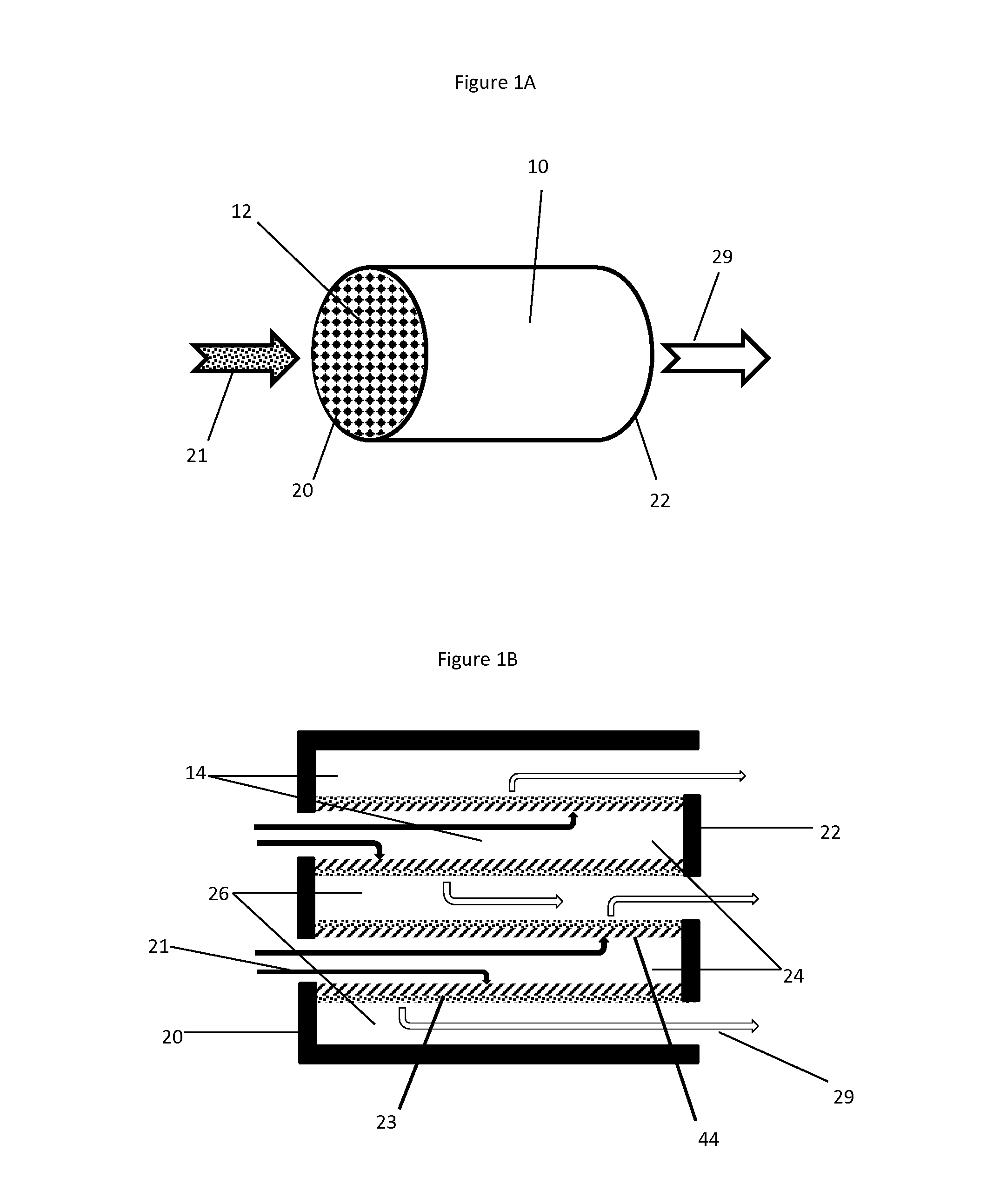
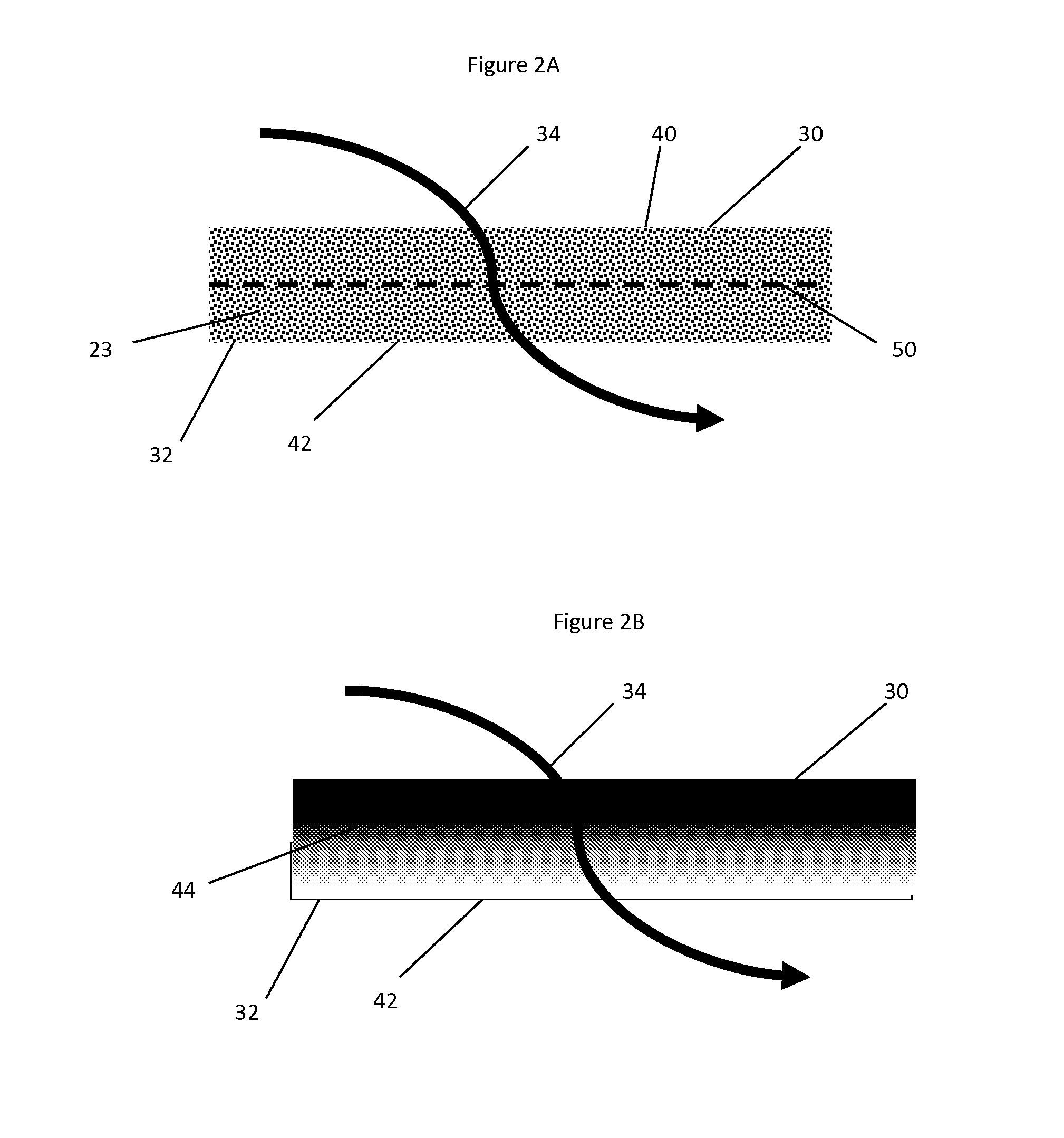
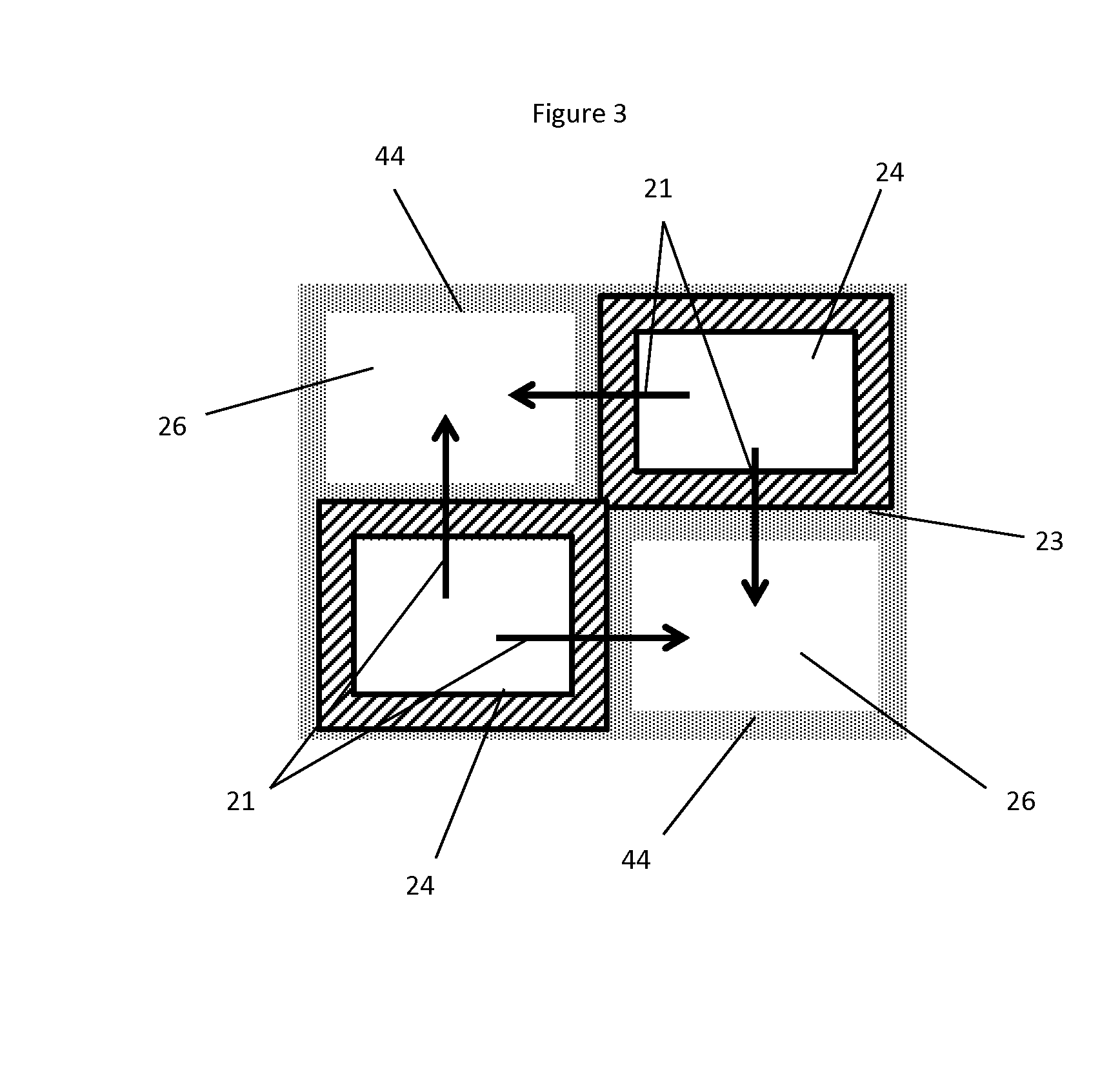
Provided is a diesel particulate filter capable of removing soot from an exhaust gas while operating at low backpressure, the filter comprising (a) a wall-flow filter substrate having a mean pore size, an inlet side, an outlet side, and a porous interior between the inlet and outlet sides; and (b) a catalyst composition coated from the inlet side of the substrate, wherein the catalyst composition has a d50 particle size distribution, wherein the d50 particle size distribution is less than the mean pore size divided by 4.9, and wherein the outlet side is substantially free of a catalyst coating.
Description
BACKGROUND[0001]1. Field of Invention[0002]The present invention relates to articles for treating combustion exhaust gas. More particularly, the present invention relates to particulate filters coated with a catalyst for reducing soot and other undesirable components from lean burn combustion exhaust gas.[0003]2. Description of Related Art[0004]The largest portions of most combustion exhaust gases contain relatively benign nitrogen (N2), water vapor (H2O), and carbon dioxide (CO2); but the exhaust gas also contains in relatively small part noxious and / or toxic substances, such as carbon monoxide (CO) from incomplete combustion, hydrocarbons (HC) from un-burnt fuel, nitrogen oxides (NOx) from excessive combustion temperatures, and particulate matter (mostly soot). To mitigate the environmental impact of exhaust gas released into the atmosphere, it is desirable to eliminate or reduce the amount of these undesirable components, preferably by a process that does not generate other noxio...
Claims
Login to View More Application Information
Patent Timeline
 Patent Type & AuthorityApplications(United States)
IPC IPC(8): B01D53/94
CPCB01D53/9472F01N3/0222F01N3/035F01N2330/30F01N2510/0682Y02T10/12
InventorCHEN, HAI-YINGDE, DEBNATHMANNING, WENDYCOX, JULIAN PETER
OwnerJOHNSON MATTHEY PLC