Conversion element, component and process for producing a component

a technology of conversion elements and components, applied in the direction of chemistry apparatus and processes, semiconductor devices, and light-emitting compositions, to achieve the effects of reducing the number of components

Active Publication Date: 2017-06-27
OSRAM OPTO SEMICONDUCTORS GMBH & CO OHG
View PDF17 Cites 3 Cited by
  • Summary
  • Abstract
  • Description
  • Claims
  • Application Information

AI Technical Summary

Benefits of technology

[0010]The inventors have realized that the conversion element described herein, in particular the matrix material has a very low sintering point and is thus very suitable for temperature-sensitive phosphors. Furthermore, the matrix material has a low softening temperature. Said matrix material is highly transparent and / or highly refractive. The matrix material also has a low crystallization tendency. It is additionally corrosion-resistant, in particular in warm, humid atmospheres, such as, for example, a humidity test at 85° C. and 85% rel. humidity over 1000 hours. The matrix material in the conversion element is thus very suitable for optical uses. A lower scattering on the basis of the low refractive index difference between matrix material and phosphor is the result. Furthermore, efficiency can be increased when using the conversion element in a component, as the heat can be better dissipated from the phosphor via the matrix material and the phosphor suffers less damage.
[0083]In the event of a separate platelet, the platelet may be positioned on the semiconductor chip before sinking and thus simultaneously bond with the chip during the sinking process. The radiation exit surface as well as the lateral surfaces can be coated with the same phosphor as well as with other phosphor types. Alternatively, both radiation exit surfaces can be coated with phosphor, wherein the same or different phosphors can be used on the two surfaces. The latter case (separation of the phosphors) allows the remission losses to be reduced (compared with the mixture within one layer).

Problems solved by technology

In particular, this is a challenge for temperature-sensitive non-oxidic phosphors.

Method used


Image

  • Conversion element, component and process for producing a component
  • Conversion element, component and process for producing a component
  • Conversion element, component and process for producing a component

Examples


Embodiment Construction

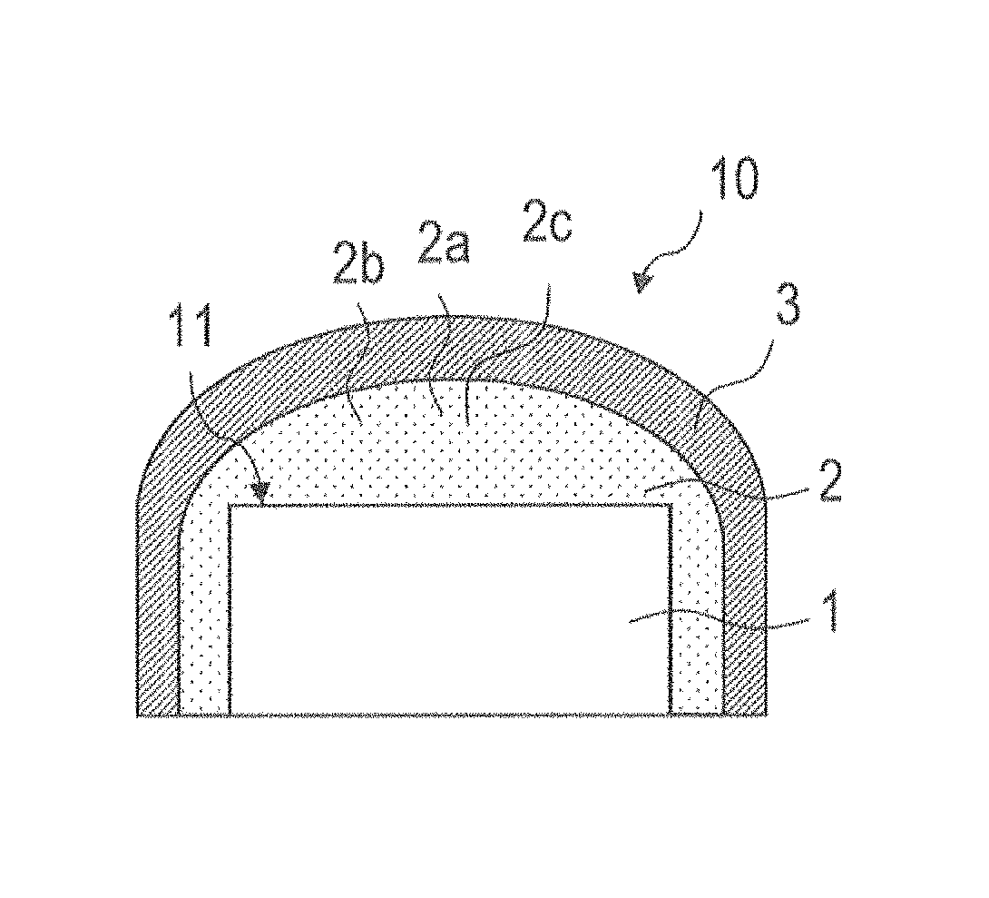
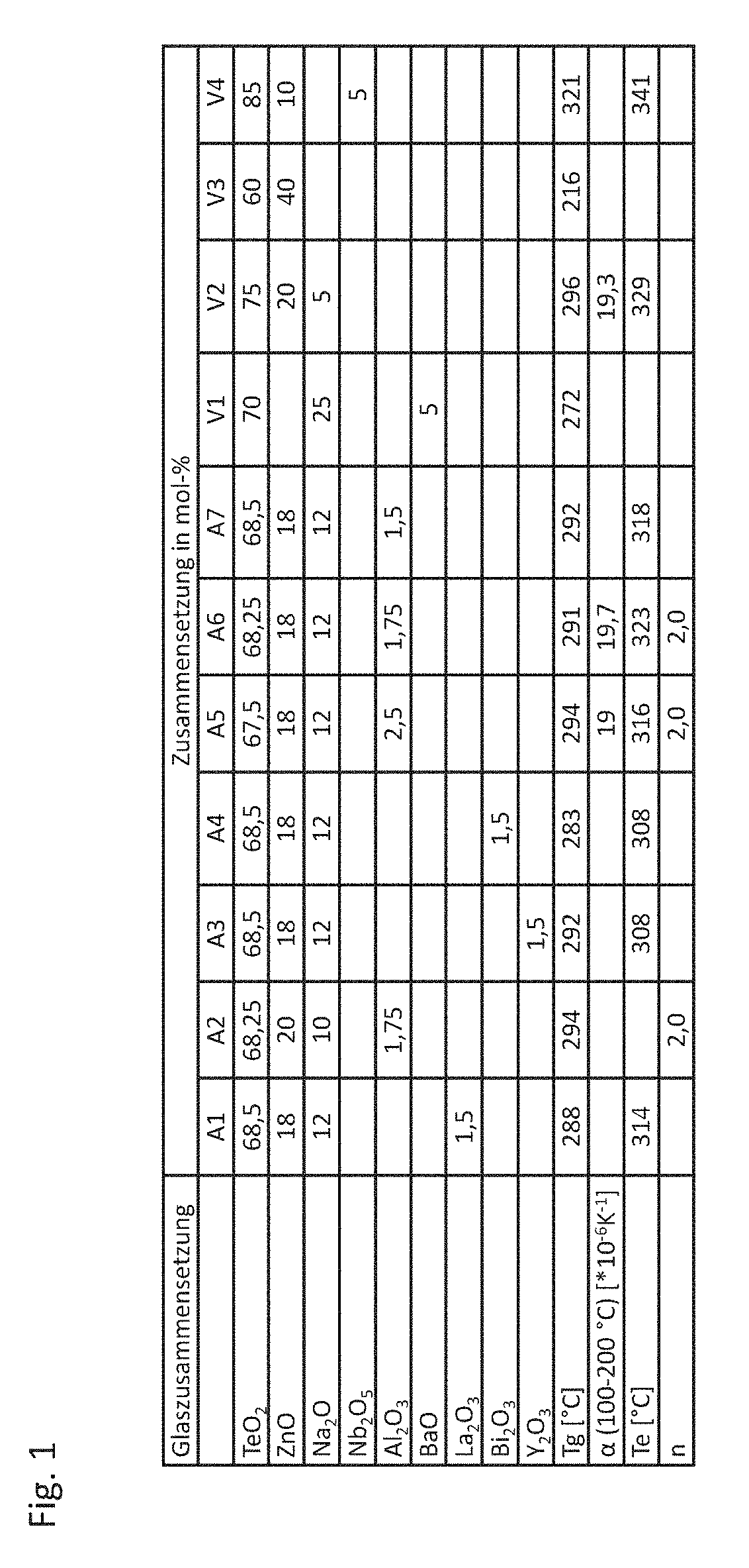
[0094]FIG. 1 shows embodiments A1 to A7 of the matrix material in tabular form. The table also shows comparative examples V1 to V4 of conventional matrix materials. The values stated in the table indicate a maximum error of 5%. No phosphor is embedded in this matrix material. The matrix material of the embodiments A1 to A7 comprises tellurium oxide, in particular tellurium oxide TeO2. The proportion of tellurium oxide in A1 to A7 equals between 67 mole % and 69 mole %. In particular, the proportion of tellurium oxide equals between 67.5 mole % and 68.5 mole % inclusively.

[0095]The matrix material further comprises R1O as zinc oxide. The proportion of zinc oxide equals between 18 mole % and 20 mole % inclusively.

[0096]The matrix material further comprises M12O in the form of disodium oxide. The proportion of disodium oxide in the matrix material equals between 10 mole % and 12 mole % inclusively.

[0097]The matrix material further comprises an oxide of a trivalent metal, such as, for e...


PUM

PropertyMeasurementUnit
dilatometric softening temperatureaaaaaaaaaa
wavelength rangeaaaaaaaaaa

Abstract

A conversion element, a component and a method for producing the component are disclosed. In an embodiment the conversion element includes a phosphor configured to convert electromagnetic primary radiation into electromagnetic secondary radiation and a glass composition as matrix material in which the phosphor is embedded. The glass composition has the following chemical composition: at least one tellurium oxide with a proportion of 65 mole % as a minimum and 90 mole % as a maximum, R1O with a proportion of between 0 mole % and 20 mole %, at least one M12O with a proportion of between 5 mole % and 25 mole %, at least one R22O3 with a proportion of between 1 mole % and 3 mole %, M2O2 with a proportion of between 0 mole % and 2 mole %, and R32O5 with a proportion of between 0 mole % and 6 mole %.

Description

[0001]This patent application is a national phase filing under section 371 of PCT / EP2014 / 077824, filed Dec. 15, 2014, which claims the priority of German patent application 10 2013 226 630.8, filed Dec. 19, 2013, each of which is incorporated herein by reference in its entirety.TECHNICAL FIELD[0002]A conversion element is provided. A component as well as a method for producing such a component are also provided.BACKGROUND[0003]A conventional conversion element usually comprises silicone as matrix material in which the phosphor is present in an embedded state. However, silicone demonstrates poor heat conductivity, which causes the phosphor to heat up more intensely during operation and thus become less efficient. In addition, the refractive index of silicone equals approximately 1.4 and perceptibly differs from that of garnet phosphors, for example, the refractive index of which equals approximately 1.8. This difference leads to a stronger scattering, in particular if very small phos...

Claims


Application Information

Patent Timeline
Patent Type & Authority Patents(United States)
IPC IPC(8): H01L33/50C09K11/02C03C3/12C03C4/12C03C14/00
CPCC09K11/025C03C3/122C03C3/125C03C4/12C03C14/006C09K11/02H01L33/502C03C2204/02C03C2214/16C03C2214/30H01L2933/0041C09K11/08H01L33/501H01L33/504
Inventor EBERHARDT, ANGELAWILLE, CHRISTINA
Owner OSRAM OPTO SEMICONDUCTORS GMBH & CO OHG
Why Eureka
Try Eureka