Opto-electric hybrid board, and production method therefor

a hybrid board and opto-electric technology, applied in the direction of conductive pattern formation, printed circuit non-printed electric components association, instruments, etc., can solve the problems of liable light transmission loss of the flexible optical waveguide w other than the boundary, liable to break or fold at the boundary, etc., to achieve easy provision of inventive opto-electric hybrid boards, reduce the light transmission loss of the resulting optical waveguide, and avoid unnecessary steps

Active Publication Date: 2017-07-11
NITTO DENKO CORP
View PDF8 Cites 6 Cited by
  • Summary
  • Abstract
  • Description
  • Claims
  • Application Information

AI Technical Summary

Benefits of technology

[0007]In the opto-electric hybrid board in which the opto-electric module portion E reinforced with the metal reinforcement layer 11 is connected to the flexible optical waveguide W, however, the optical waveguide W is liable to be pulled and twisted by the highly rigid metal reinforcement layer 11 at a boundary between the opto-electric module portion E and the optical waveguide W whenever the optical waveguide W is moved. Therefore, the optical waveguide W is liable to be broken or folded at the boundary. Further, a portion of the flexible optical waveguide W other than the boundary is liable to suffer from a slight light transmission loss. It is also strongly desirable to protect the optical waveguide W from the breakage and the folding in an entirely flexible opto-electric hybrid board not provided with the metal reinforcement layer 11.
[0008]In view of the foregoing, it is an object of the present invention to provide an excellent opto-electric hybrid board which includes a sufficiently flexible interconnection portion including an optical waveguide protected from bending and twisting and is substantially free from increase in light transmission loss, and to provide a production method for the opto-electric hybrid board.

Problems solved by technology

Therefore, the optical waveguide W is liable to be broken or folded at the boundary.
Further, a portion of the flexible optical waveguide W other than the boundary is liable to suffer from a slight light transmission loss.

Method used


Image

  • Opto-electric hybrid board, and production method therefor
  • Opto-electric hybrid board, and production method therefor
  • Opto-electric hybrid board, and production method therefor

Examples


example 1

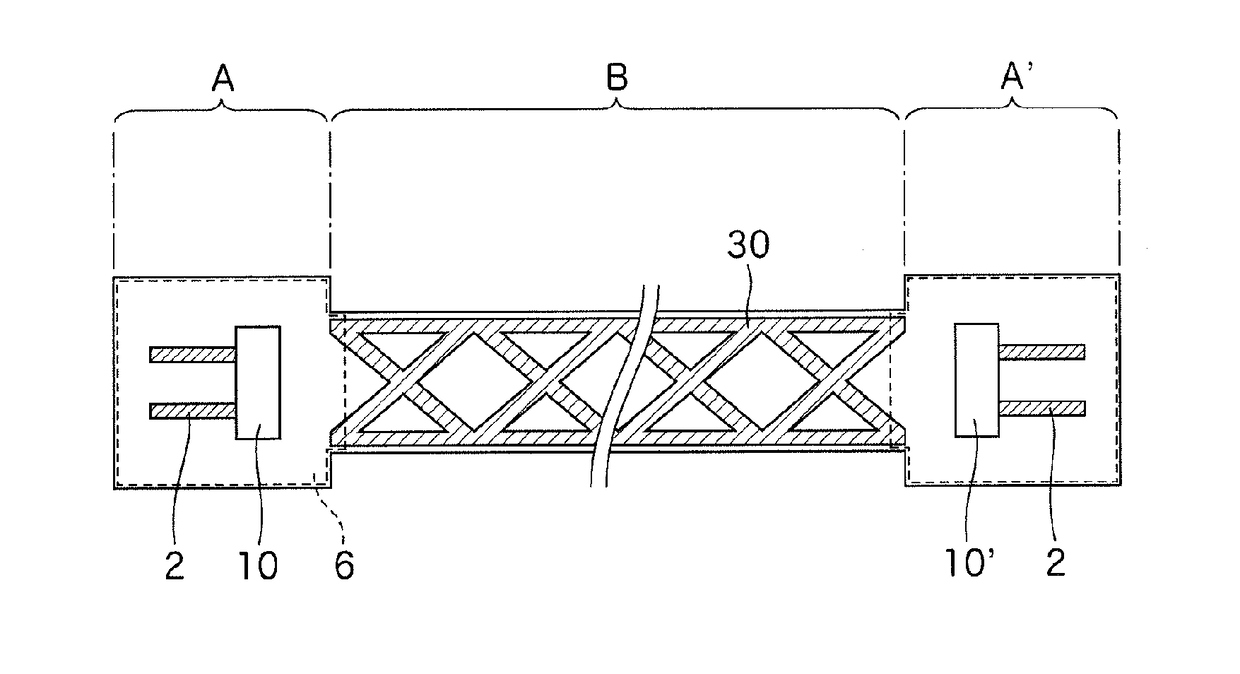
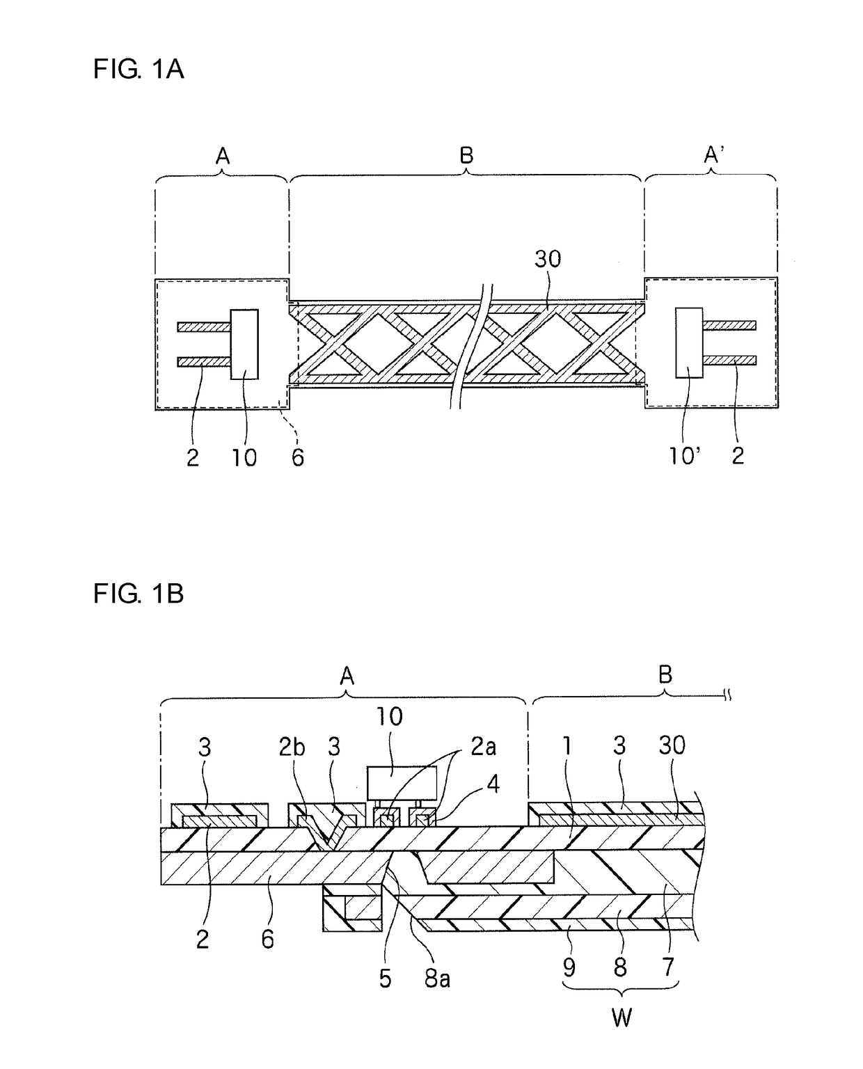
[0068]The opto-electric hybrid board shown in FIGS. 1A and 1B was produced in the aforementioned manner. The interconnection portion B had a length of 20 cm. A 20-μm thick stainless steel layer was provided as the metal reinforcement layer. The insulation layer had a thickness of 5 μm, and the under-cladding layer had a thickness of 10 μm (as measured from the back surface of the insulation layer). The core had a thickness of 50 μm and a width of 50 μm. The over-cladding layer had a thickness of 70 μm (as measured from the front surface of the under-cladding layer). The first electric wiring and the electrically conductive dummy pattern had a thickness of 5 μm. The electrically conductive dummy pattern had an oblique lattice shape, and covered the insulation layer at a surface coverage percentage of 44%. The electrically conductive dummy pattern had edge portions respectively extending continuously along the opposite longitudinal edges of the interconnection portion and each having ...

example 2

[0069]An opto-electric hybrid board having substantially the same basic construction as in Example 1, except that electrically conductive dummy patterns were formed in an arrangement as shown in FIG. 7 and no second electric wiring was formed. The electrically conductive dummy patterns covered the surface of the insulation layer at a surface coverage percentage of 40%. Longitudinal edge portions of the electrically conductive dummy patterns respectively extending continuously along the opposite longitudinal edges of the insulation layer each had a width (indicated by a reference character Q′ in FIG. 7) of 400 μm.


PUM


Abstract

An inventive opto-electric hybrid board includes: opto-electric module portions respectively provided on opposite end portions of an elongated insulation layer and including a first electric wiring of a first electrically conductive pattern and an optical element provided on a front surface of the insulation layer; and an interconnection portion provided on a portion of the insulation layer extending from the opto-electric module portions, and including an elongated optical waveguide on a back surface of the insulation layer optically coupled with the optical elements, and having a light signal transmission core. Further, an electrically conductive dummy pattern is provided on the front surface of the insulation layer in the interconnection portion for reinforcing the interconnection portion. The electrically conductive dummy pattern reinforces the interconnection portion to protect the waveguide from bending and twisting, while ensuring the flexibility of the interconnection portion. This suppresses increase in light transmission loss.

Description

TECHNICAL FIELD[0001]The present invention relates to an opto-electric hybrid board including an opto-electric module portion and an interconnection portion, and to a production method therefor.BACKGROUND ART[0002]In recent electronic devices and the like, optical wirings are employed in addition to electric wirings to cope with increase in information transmission amount. With a trend toward size reduction of the electronic devices and the like, there is a demand for a wiring board which has a smaller size and a higher integration density so as to be mounted in a limited space. An opto-electric hybrid board as shown in FIG. 10, for example, is proposed as such a wiring board. In the opto-electric hybrid board, an opto-electric module portion E including an electric wiring 13 of an electrically conductive pattern and an optical element 10 is provided on each (or one) of opposite end portions of a front surface of an insulation layer 12 such as of a polyimide, and an optical waveguid...

Claims


Application Information

Patent Timeline
Patent Type & Authority Patents(United States)
IPC IPC(8): G02B6/42H05K3/30H05K3/24H05K3/10G02B6/122H05K1/18G02B6/43H05K1/02G02B6/13
CPCG02B6/428G02B6/122G02B6/13G02B6/4283G02B6/43H05K1/0274H05K1/181H05K3/10H05K3/24H05K3/301G02B6/4214G02B6/4281H05K1/0281H05K2201/10121H05K2201/2009
Inventor TSUJITA, YUICHISHIBATA, NAOKI
Owner NITTO DENKO CORP
Why Eureka
Try Eureka