Directional light transmitter and receiver

a directional light transmitter and receiver technology, applied in the direction of electromagnetic transmission, electromagnetic transmission optical aspects, electrical equipment, etc., can solve the problems of increasing the risk of health effects of electromagnetic transmission, needing to recharge the battery, and increasing the power consumption. achieve the effect of energy efficient and safe manner

Active Publication Date: 2017-07-11
WI CHARGE
View PDF65 Cites 7 Cited by
  • Summary
  • Abstract
  • Description
  • Claims
  • Application Information

AI Technical Summary

Benefits of technology

[0015]The present invention seeks to provide a system and method of supplying energy wirelessly to a portable electrically or optically powered mobile device, in an energy efficient and safe manner. According to the current invention, the transmission is stopped when no receiver is present within a line of sight of the transmitter, and does not require the use of a directional servo system, while providing accuracy in directing the beam from the transmitter to the receiver. The energy is transferred as a safe beam that stops almost instantaneously when there is no line of sight between the receiver and the transmitter.
[0016]The system of the present invention preferably comprises two parts—a power transmitter and a power receiver. The power transmitter comprises a light amplifier and a light retro-reflector. The purpose of the light amplifier is to amplify photons received from the receiver and the purpose of the retro-reflector is to reflect those amplified photons back to the receiver, preferably through the amplifier which will amplify them even more. Such an amplifier can be in the form of a laser gain medium (such as Nd+YAG, Er+YAG, or a semiconductor such as GaAlAs) which is in a population inversion mode, allowing for amplification of the photons passing through.
[0041]In any of the above described embodiments, whether for a system for transmitting power wirelessly, or for a free-space lasing system, the transmitting unit may further comprise a detector for measuring the amount of radiation received, the detector being operative to perform at least one of the decoding of data and the increasing of the safety of the system. The increased safety of the system may preferably be achieved by utilizing the detector to detect a change in the level of radiation outside of the optical path between the transmitting and the receiving units. Furthermore, the receiver unit may further comprise a second detector for measuring the amount of radiation received, the second detector being operative to perform at least one of the decoding of data and the increasing of the safety of the system. The increased safety of the system may preferably be achieved by utilizing the second detector to detect a change in the level of radiation outside of the optical path between the transmitting and the receiving units.
[0045]There is even further provided in accordance with a preferred embodiment of the present invention, a wireless power receiver comprising a retro reflector and a light coupler capable of converting optical power into electrical power, wherein the receiver is adapted to receive power wirelessly from a remote transmitter unit. This wireless power receiver may preferably also comprise a wireless data link for transmission of the status of the receiver. The retro reflector may preferably be semi transparent, and may comprise at least one cube corner retro reflector. In such a wireless power receiver, reflections in directions other than 180 degree from the incident beam direction are preferably blocked. Additionally, the retro reflector may be a hollow corner retro reflector, such that undesired surface reflections from the retro reflector are reduced. Any such undesired surface reflections remaining may be minimized by use of anti reflective coatings.
[0047]Furthermore, in accordance with yet another preferred embodiment of the present invention, there is further provided a method of directing radiation in a system between a transmitting unit capable of lasing at more then a single wavelength, and a receiver unit having a characteristic wavelength response by adapting the transmitting unit to preferentially lase at the characteristic wavelength such that the receiver unit has a more efficient optical coupling to the transmitter than other receiver units having a different characteristic wavelength response.

Problems solved by technology

One of the most common drawbacks of such devices is the need for recharge of the battery (in the case of a rechargeable battery) or replacement of the battery (in the case of a non rechargeable battery).
Another drawback of such devices, if they are such as to transmit and receive data, is the requirement to transmit data in all directions, to ensure that it will be picked up by the base station, which increases power consumption significantly, as well as increasing any health risks associated with electromagnetic transmissions.
Firstly, if the beam is blocked the radiation continues, in the case of a high energy beam health risk and potential damage to objects crossing the beam's path pose a significant limitation on the use of such a device.
There are two significant problems associated with such a servo mechanism, first, it can fail, directing the beam into unwanted places, second it complicates the transmitter and adds to its price.
Should the same principle be used to transmit power over larger distances, two problems may be encountered, first the efficiency of transmission may drop significantly and second, if a mobile receiver is to be used, a servo mechanism with its associated risks and price may have to be added to the device.
In most of the above methods, the transmitter can transmit power in directions where there is no receiver, the generated radiation may be harmful, especially if it is not blocked by the receiver or if the servo mechanism fails to direct it there.
However such a mechanism has a number of drawbacks: It has moving parts that may fail over time, with possibly reduced reliability.
It can, in error, or due to a fault of the system, hit an object sensitive to the energy beam (such as a human eye) and cause harm to it.
Power may be lost due to imperfect direction of the beam, causing inefficiency and further possible damage to the surroundings.
It would also be difficult, using a single laser, or an ultrasound or microwave beam, to transmit power to more than one device.
Lastly, a directional beam which has no fool proof mechanism to stop it in case the beam is blocked cannot transmit large amounts of power and still meet safety requirements.
However it is the nature of such an isotropic or pseudo-isotropic method of propagating radiation, that the power falls off very quickly with distance, so the power consumption of such a transmitter would need to be high or the range limited.
Another drawback of such an approach is the various health hazards and inconveniences.

Method used


Image

  • Directional light transmitter and receiver
  • Directional light transmitter and receiver
  • Directional light transmitter and receiver

Examples


Embodiment Construction

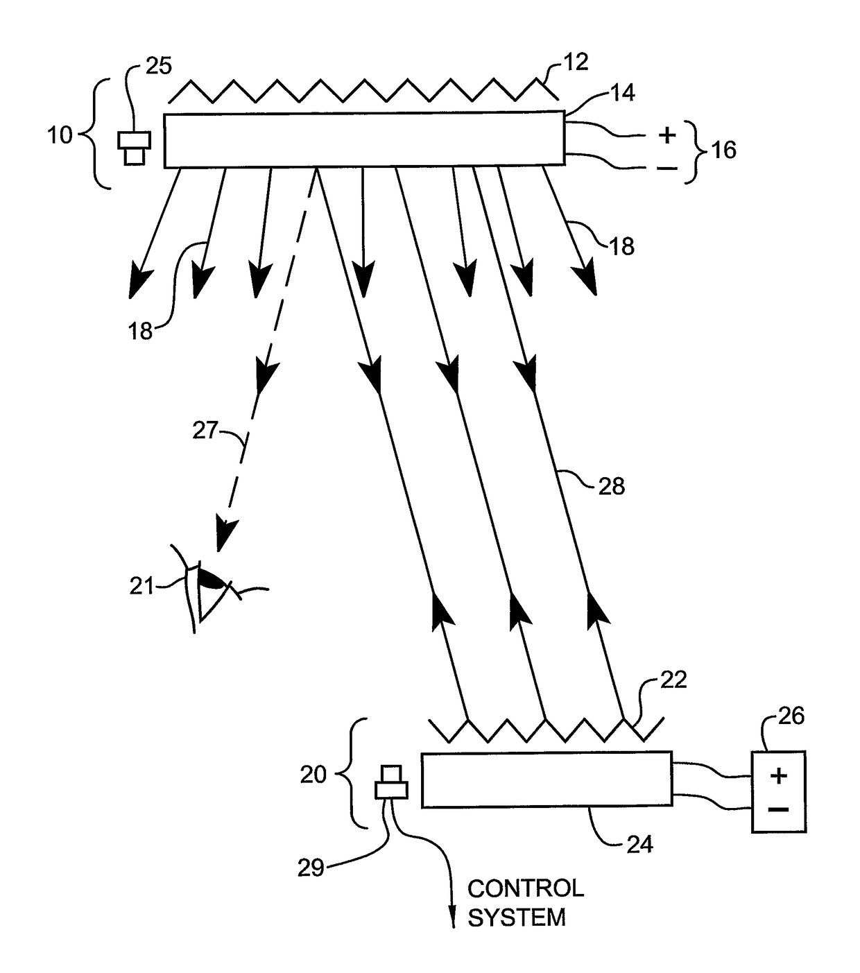
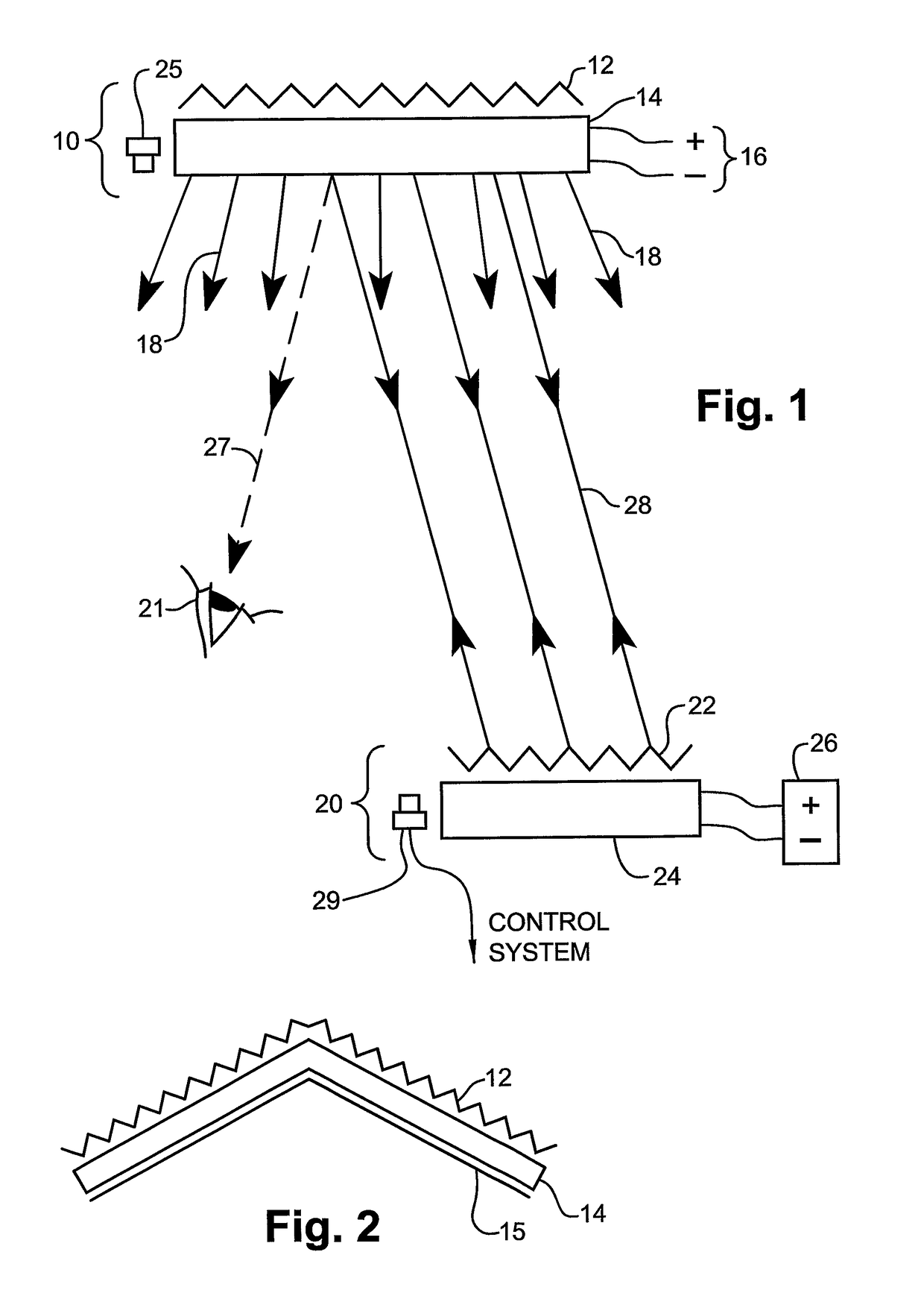
[0058]Reference is now made to FIG. 1, which is a schematic illustration of a complete transmission and reception system, constructed according to a first preferred embodiment of the present invention. The transmitter 10, preferably mounted in a position where it can radiate into the whole of the volume to be covered, comprises a 3-dimensional retroreflector array 12, in front of which is disposed a gain material 14, preferably excited by means of an electrical excitation input 16, though other forms of excitation such as optical or chemical pumping can equally be used with suitable gain media. The gain material is preferably provided with anti-reflection optical coatings to improve its performance, as is known in the art.

[0059]When the excitation generates a population inversion in the gain material 14, it will emit photons in all directions 18. In the absence of a receiver, these photons will generally be absorbed by the surroundings, and since their flux level is low, they presen...


PUM


Abstract

A system for supplying power wirelessly to a remote mobile device including (i) a transmitting unit for directing radiation into the region of the mobile device, the transmitting unit having a gain medium with a front surface directed towards the space, and a retroreflector on its back surface, and (ii) a receiver unit connected with or attached to the mobile device for receiving radiation transmitted from the transmitting unit. The receiver unit includes (i) a retroreflector for reflecting part of the radiation received from the transmitting unit back in the direction of the transmitting unit, where it is amplified and retransmitted back in the direction of the receiver unit, and (ii) a power detection element for absorbing that part of the radiation not reflected by the retroreflector, and converting it to electrical power for use by the mobile device. Modulation of the transmitted beam enables it to transmit data also.

Description

CROSS REFERENCE TO PRIOR APPLICATIONS[0001]This application is the U.S. national phase of International Application No. PCT / IL2006 / 001131 filed Sep. 27, 2006, which claims priority from U.S. Patent Application No. 60 / 720,648 filed Sep. 27, 2005. The international application published in English on Apr. 5, 2007 as WO 2007 / 036937 A2.FIELD OF THE INVENTION[0002]The present invention relates to the field of the wireless transmission of power and data to a remote, low power device over free space, in a safe, efficient manner.BACKGROUND OF THE INVENTION[0003]In recent years many low power mobile devices have come into use. In many cases these devices use a battery to provide electric power, in other cases they draw their power from another device such as a computer (through a USB port for example). Many of these devices are also used to transmit and receive data. Devices that use the Bluetooth protocol are good examples of such devices.[0004]One of the most common drawbacks of such devic...

Claims


Application Information

Patent Timeline
Patent Type & Authority Patents(United States)
IPC IPC(8): H04B10/00H04B10/80
CPCH04B10/807H04B10/1123H04B10/11
Inventor ALPERT, ORTAL
Owner WI CHARGE
Why Eureka
Try Eureka