
Interlocked stator yoke and star for electric motor

a technology of electric motors and stators, applied in the direction of dynamo-electric machines, electrical apparatus, magnetic circuit shapes/forms/construction, etc., can solve the problems of difficult control of process, increased part cost due to process labor and iron scrap, and limited in reaching high efficiency versus cost and package targets. achieve the effect of less effort, better lamination alignment, and more freedom degrees

Active Publication Date: 2017-07-18
HANON SYST EFP DEUT GMBH
View PDF30 Cites 1 Cited by
  • Summary
  • Abstract
  • Description
  • Claims
  • Application Information

AI Technical Summary

Benefits of technology

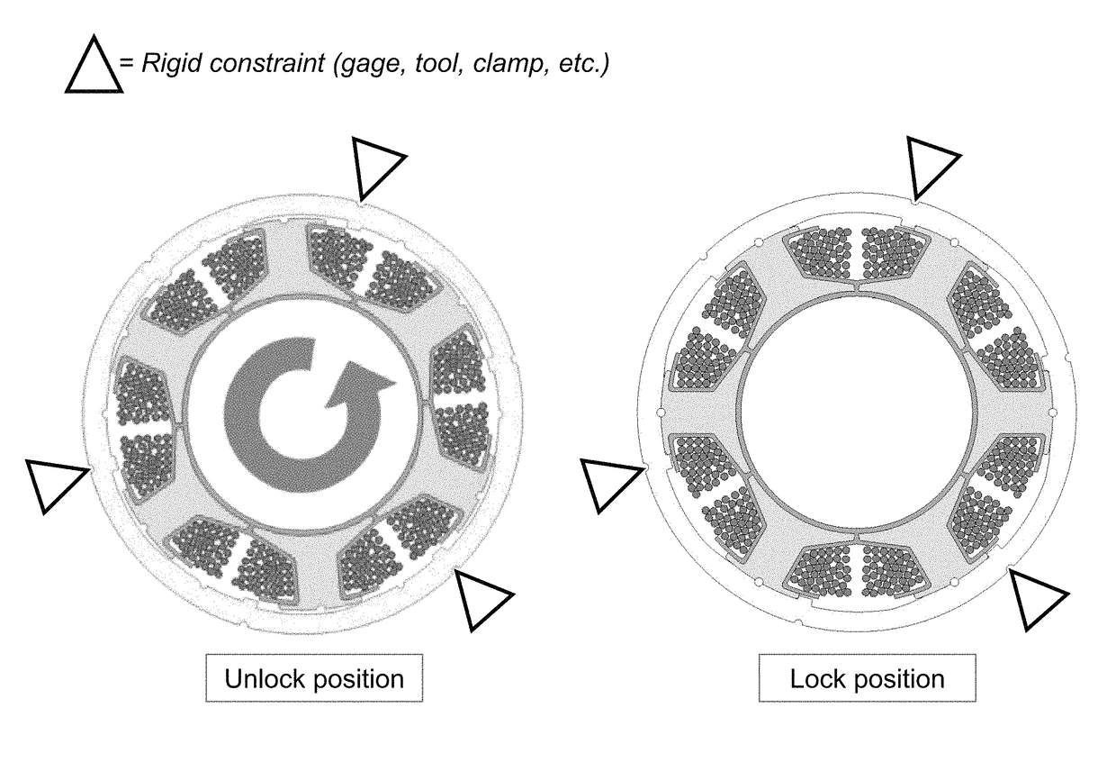
The present invention provides a stator construction for an electric motor that has the star and yoke components of a stator as a single lamination, with the components of the lamination being stamped or punched in "one shot". This results in a more efficient motor with better lamination alignment and a higher copper filling factor. The stator winding is easy to externalize and has low iron losses between yoke / stator star contact areas. The interlocking of the yoke and stator star is easy, and the cost of the process is reduced due to fewer punches and scrap material.

Problems solved by technology

Typically, a one-component stator is inexpensive and heavily used in standard inner rotor motors, but has limits in the winding process (copper wire diameter, filling factor, inner diameter, and the like) and as a consequence is limited in reaching high efficiency versus cost and package targets.
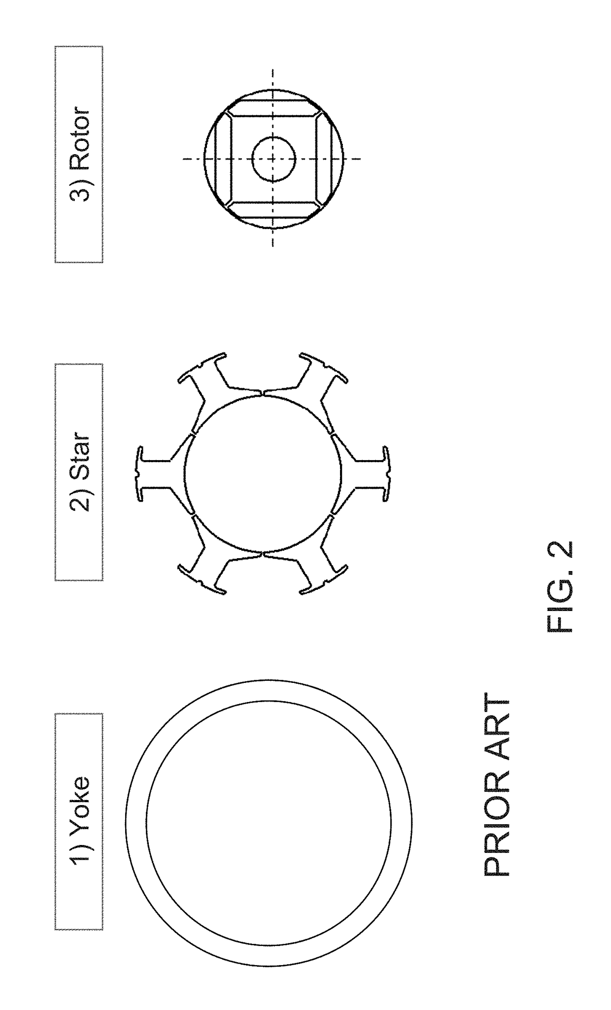
Such a stator construction may allow for improved winding with high copper diameter and filling factor but it generates several disadvantages, including (i) high and variable insertion forces required to press the star into the yoke, which makes the process difficult to control, (ii) the necessity to cut the two parts of the stator in different punching stations, in order to have a better dimensional control and for reducing the insertion force issues, which increases the part cost due to process labor and iron scrap, and (iii) iron losses generated by electrical contacts due to interference and not perfect alignment between yoke / star lamination (eddy currents in excess that downgrade the laminations grade).

Method used


Image

  • Interlocked stator yoke and star for electric motor
  • Interlocked stator yoke and star for electric motor
  • Interlocked stator yoke and star for electric motor

Examples


Embodiment Construction

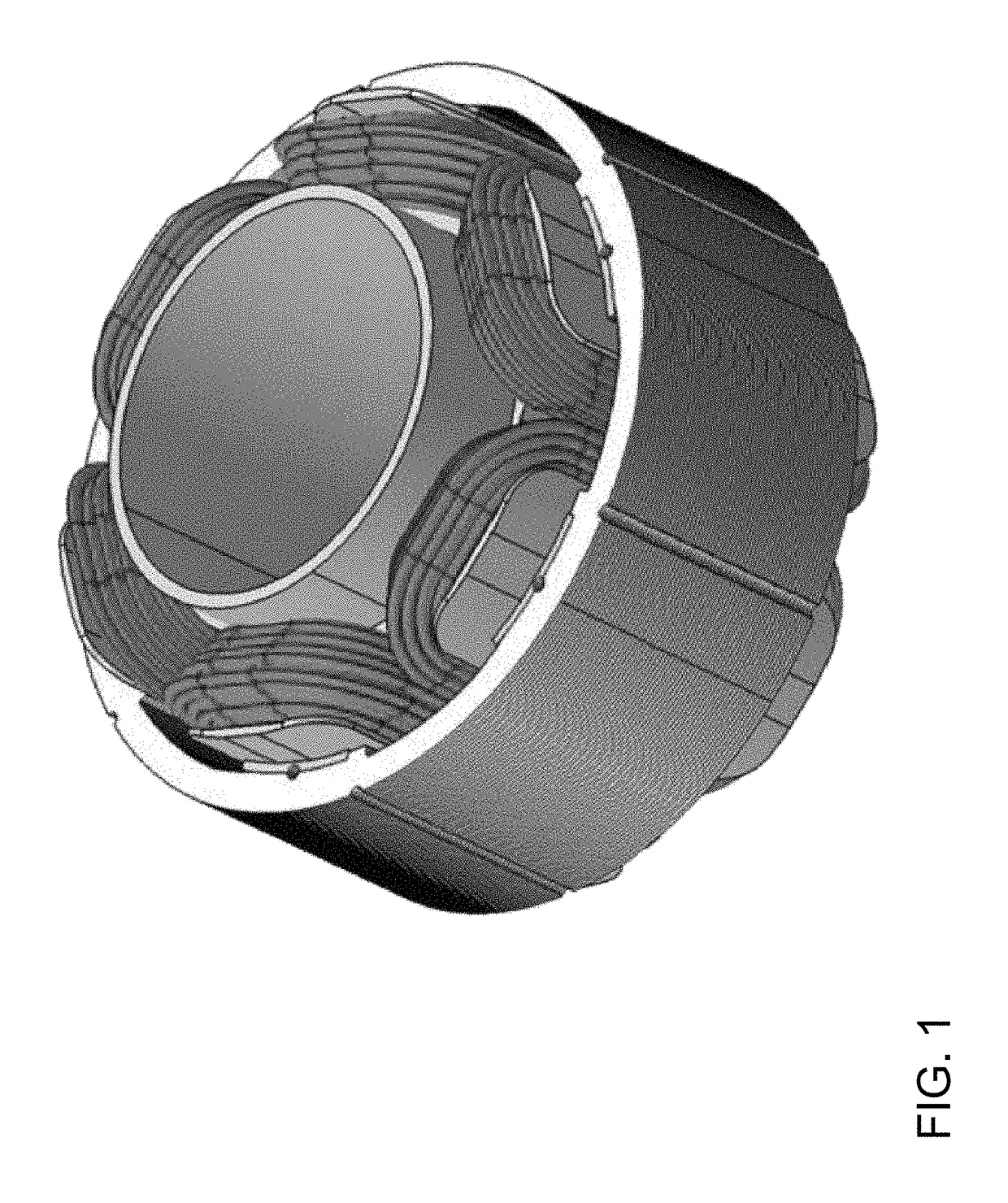
[0023]Referring now to the drawings and the illustrative embodiments depicted therein, a stator of the present invention comprises a yoke and a star, which are joined together and which rotate about a rotor (FIGS. 1, 5 and 6). The yoke and star are formed so that the star (which may be laminated and comprise a plurality of layers of star elements) may be readily inserted axially into the yoke (which may be laminated and comprise a plurality of layers of yoke elements) and then rotated relative to the yoke to provide a tight interference fit between the yoke and star. The yoke and star elements (and optionally the rotor too) may be punched via a common punching process so that, when the star and yoke are assembled together, the interference fit between the components is tight and consistent.

[0024]The present invention designs the separation surfaces between the stator yoke and the separate teeth of the star so that they can be assembled, after winding of the wire onto the star, with ...


PUM


Abstract

A stator for an electric motor includes a yoke and a star disposed in the yoke. The star is configured to receive a rotor therein and has at least one wire coiled thereat. The yoke and the star are configured such that the star is axially insertable into the yoke with reduced interference and reduced insertion force. The star is axially inserted into the yoke in an unlocked position. When the star is inserted into the yoke, the star is rotatable to a locked position, whereby the star is retained at the yoke via an interference fit.

Description

CROSS REFERENCE TO RELATED APPLICATION[0001]The present application claims the filing benefits of U.S. provisional application, Ser. No. 61 / 869,195, filed Aug. 23, 2013, which is hereby incorporated herein by reference in its entirety.FIELD OF THE INVENTION[0002]The present invention relates electrical motors and, more particularly, to stators for electric motors with internal rotors.BACKGROUND OF THE INVENTION[0003]Typically, a one-component stator is inexpensive and heavily used in standard inner rotor motors, but has limits in the winding process (copper wire diameter, filling factor, inner diameter, and the like) and as a consequence is limited in reaching high efficiency versus cost and package targets.[0004]Two-component stator designs are known. Typically, a two-component stator consists of cutting a ring for a stator yoke and a separate cutting a star which, once separately wound, is then axially pressed into the rotor yoke. Such a stator construction may allow for improved ...

Claims


Application Information

Patent Timeline
Patent Type & Authority Patents(United States)
IPC IPC(8): H02K1/18H02K1/12H02K1/14H02K15/02
CPCH02K1/18H02K1/12H02K1/148H02K15/02H02K15/022H02K15/028
Inventor ARNOLDI, ERNESTO G.MAURINO, PAOLO L.AVIDANO, MAURIZIO
Owner HANON SYST EFP DEUT GMBH
Learn More