Method and apparatus for measuring the temperature of a molten metal

a technology of molten metal and temperature measurement, which is applied in the direction of heat measurement, optical radiation measurement, instruments, etc., can solve the problems of unintentional de-slagging, unfavorable use of heat exchangers, and only 55-65% energy efficiency of steelmaking, and achieve the effect of low cos

Active Publication Date: 2017-08-08
HERAEUS ELECTRO NITE INT NV
View PDF52 Cites 6 Cited by
  • Summary
  • Abstract
  • Description
  • Claims
  • Application Information

AI Technical Summary

Benefits of technology

[0029]The invention of the present application works away from the prior teaching, preferring to provide a spot measurement rather than a continuous measurement. Invented is a low cost solution for temperature measurements suitable to be utilized at a sufficiently high sampling frequency to meet the updating demands of the mathematical models of the EAF melting process, while solving the problems associated with immersed optical fiber in harsh environments. The invention provides a near continuous temperature measuring output comprised of immersing an optical fiber into the molten metal through the slag covering without first contacting the slag, maintaining a predetermined immersion depth during the measuring period by controlled feeding, protecting the non-immersed portion against devitrification in the high ambient heat of the EAF interior, removing and recoiling unused fiber after the measurement, measuring the bath level upon recoiling, and immersion equipment for repeating the measuring processes always duplicating the initial starting conditions.
[0030]The invention measures temperature in a metallurgical vessel using a molten metal immersed consumable optical fiber and immersion equipment capable of inserting a temperature device through the side wall of an EAF to a predictable molten steel immersion depth with a temperature-to-temperature measuring frequency of less than 20 seconds. The ability to sample on-demand, singularly or in rapid succession allows a measuring strategy that can update a mathematical predictive model for EAF operations at key times during the process, with the ability to measure in rapid succession providing near continuous temperature data at a low cost.

Problems solved by technology

However, EAF steelmaking is only 55-65% energy efficient and as a result the total equivalent energy input is usually in the range of 650 kWh / t for most modern operations with 60-65% supplied by electric power, and the remaining requirements supplied by fossil fuel combustion and the chemical oxidation energy of the refining process.
This process will create a lot of heat in the slag layer covering the steel, resulting in temperatures that are up to 200° C. higher than the steel temperature and creating a very unique and difficult environment for process control measurements for reasons explained later.
During arcing, nitrogen is converted to NOx which is an undesirable effluent of the EAF process.
While it is necessary to de-slag the furnace through this opening, the use of robotic immersion equipment also utilizing this opening to take temperatures, exposes the furnace interior to unnecessary nitrogen ingress and unintentional de-slagging during periods when repeated temperature measurements are required.
With a rapid temperature rise during the end stages of the metal refining process, the update time for a process control model under the best of circumstances cannot keep up with modern high-powered furnaces.
A realistic test-to-test time of 1 minute for typical robotic systems limits the usefulness of spot measurements of such a dynamic process.
Conventional disposable thermocouples and robotic immersion equipment suffer from several additional limitations, besides a low sampling frequency that ultimately reduces the predictive success of the process models, when used for accurate end point decisions.
Because of this, these manipulators cannot position disposable thermocouples into the bath at all times and under all circumstances.
Furthermore, the immersion depth of the thermocouple is linked to the articulation of the mechanical arm of the robotic device and as such cannot readily adjust to a bath level change, due to the angle of the furnace tilt.
While it is important to repeatedly measure in a location that reflects the bulk temperature for the purpose of the operating models of the EAF process, the actual temperature measurements taken with either a manual or automatic lance show difficulties towards stable immersion depths, not available while the position of the immersion lance is not aligned to the rocking of the furnace and the actual bath level, and not in a location conducive to temperature accuracy.
Continuous measurements of molten metals using consumable optical fiber and equipment necessary to feed long lengths of coiled material to a predetermined depth are well known in the art, such as European patent application publication EP 0 806 640 A1 and Japanese Patent JP 3,267,122 B. In harsh industrial environments where the consumable optical fiber is immersed into higher temperature metals or in the presence of metals with a slag covering, maintaining a predetermined depth during the period of time the measurement should take place has proven to be difficult due to the inherent weakness in the optical fiber as its temperature increases.
The above improvements for high temperature use have the disadvantage of dramatically increasing the cost of the consumable fiber assembly in order to provide a continuous temperature reading.
The optical fiber and its enclosing stainless steel outer tube are costly to consume at this recommended feeding rate.
While these devices can successfully deliver the fiber to the measuring point, they become a liability due to clogging and continuing maintenance.
If the port is blocked or closes due to inadequate gas pressure, the measurement is terminated with no possibility of recovering until the nozzle is repaired.
However, these are strategies to unblock a closed access port from which no measuring data can be obtained.
Once these ports are blocked there is no possibility to obtain temperature data, which could be at critical times in the steelmaking process.
An additional problem arises for continuously fed optical fibers, which further increase the cost of measurement and the complexity of the immersion equipment.
At elevated temperatures, devitrification of the optical fiber will occur, the transmissivity of the light decreases, and an error in temperature as a function of decreased intensity increases.
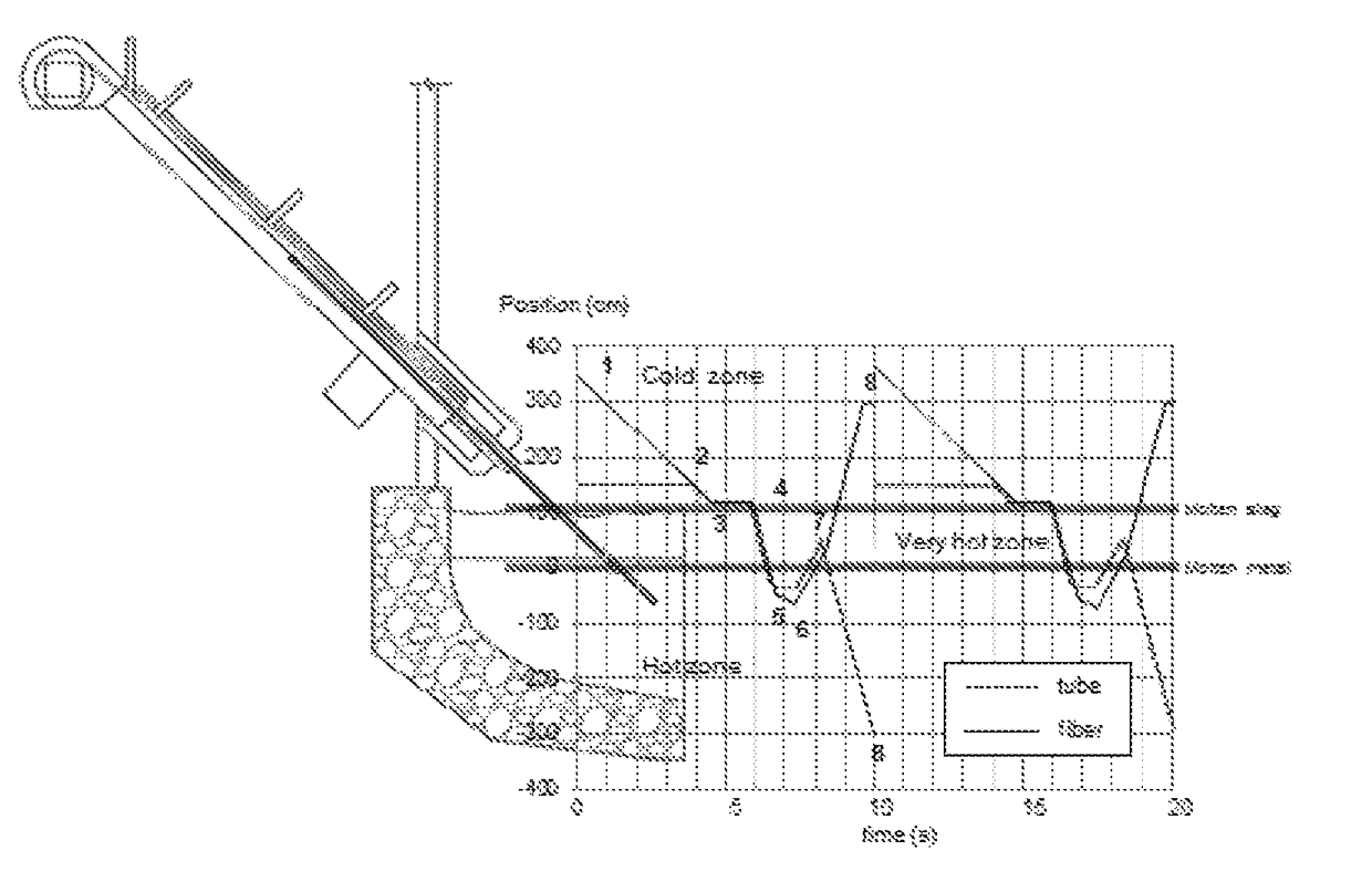
Simple laboratory testing shows that the optical signal stays stable during a very short period, being around 1.0 sec at temperatures below 1580° C. and only 0.1 sec. while immersed at 1700° C. Although a solution for lower temperature metals, the speed of feeding optical fiber at a speed greater than the devitrification rate for elevated temperature testing is expensive for a simple metal covered optical fiber.
This becomes prohibitively expensive for the above-mentioned double covered optical fibers.

Method used


Image

  • Method and apparatus for measuring the temperature of a molten metal
  • Method and apparatus for measuring the temperature of a molten metal
  • Method and apparatus for measuring the temperature of a molten metal

Examples


Embodiment Construction

[0082]The device is described as follows by way of example. FIG. 1. shows prior art consumable optical fiber 10, typically employed in the measurement of liquid metals, comprising an optical fiber, a plastic jacket covering the optical fiber and a protective metal tube covering the surface of the plastic jacket. The optical fiber 10, typically a graded index multimode fiber made of quartz glass having an inner core 11 with a diameter of 62.5 μm and an outer cladding 12 with a diameter of 125 μm covered with a polyimide or similar material 13. The protective metal tube 14 is typically stainless steel having a 1.32 mm outer diameter (OD) and 0.127 mm wall thickness. Although a metal covered optical fiber is preferred, additional embodiments where 14 and / or 13 are replaced by a singular plastic material do not depart from the intended invention.

[0083]FIG. 2 shows the leading section 10′ of a metal coated optical fiber 10, as fed from spool 20 through a gas retaining elastic plug 30, af...


PUM

PropertyMeasurementUnit
areaaaaaaaaaaa
areaaaaaaaaaaa
temperatureaaaaaaaaaa

Abstract

A method, device and apparatus are provided for measuring the temperature of a melt, particularly of a molten metal, with an optical fiber, fed into the melt through a disposable guiding tube. The optical fiber and an immersion end of the tube are immersed into the melt and have feeding speeds which are independent from each other. An elastic plug is arranged within the tube or at an end of the tube opposite the immersion end. The optical fiber is fed through the elastic plug, and the elastic plug reduces a gap between the optical fiber and the tube, which has a larger inner diameter than the outer diameter of the optical fiber. The apparatus includes a fiber coil and a feeding mechanism for feeding the optical fiber and the tube, including at least two independent feeding motors, one for feeding the optical fiber and one for feeding the tube.

Description

BACKGROUND OF THE INVENTION[0001]The invention relates to a method, a device and an apparatus for measuring the temperature of a melt, particularly of a molten metal, for example molten steel, with an optical fiber.[0002]The Electric Arc Furnace (EAF) process for the production of molten steel is a batch process made up of the following operations: furnace charging of metallic components, melting, refining, de-slagging, tapping, and furnace turnaround. Each batch of steel, called a heat, is removed from the melting furnace in a process called tapping, and hence, a reference to the cyclic batch rate of steel production is commonly a unit of time termed the tap-to-tap time. A modern EAF operation aims for a tap-to-tap cycle of less than 60 minutes and is more on the order of 35-40 minutes.[0003]Many of the advances made in EAF productivity, which make rapid tap-to-tap times possible, are related to increased electrical power input (in the range of 350-400 kWh / t), and alternative forms...

Claims


Application Information

Patent Timeline
Patent Type & Authority Patents(United States)
IPC IPC(8): G01J5/04G01J5/08B22D2/00G01J5/00G01K11/32
CPCG01J5/004B22D2/006G01J5/042G01J5/048G01J5/0821
Inventor NEYENS, GUIDO JACOBUSTHYS, MICHELSTEVENS, FRANK
Owner HERAEUS ELECTRO NITE INT NV
Why Eureka
Try Eureka