
Sensor element with temperature compensating function, and magnetic sensor and electric power measuring device which use same

a technology of temperature compensation and sensor element, which is applied in the direction of magnetic field-controlled resistors, magnetic measurements, instruments, etc., can solve the problems of harsh environment of intended use, and achieve the effect of maintaining sensitivity, reducing longitudinal bias magnetic field, and reducing sensitivity

Active Publication Date: 2017-08-22
SIRC CO LTD
View PDF13 Cites 1 Cited by
  • Summary
  • Abstract
  • Description
  • Claims
  • Application Information

AI Technical Summary

Benefits of technology

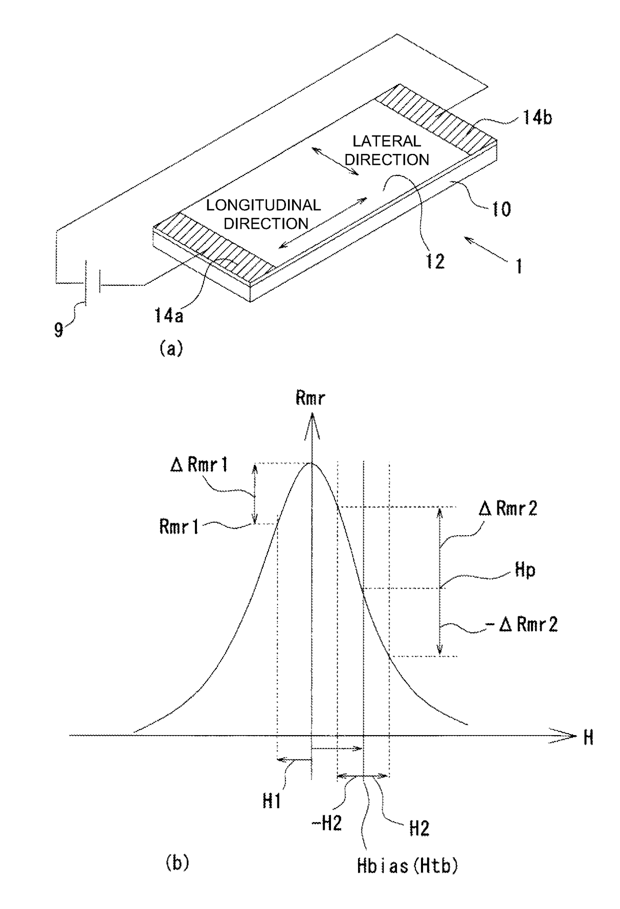
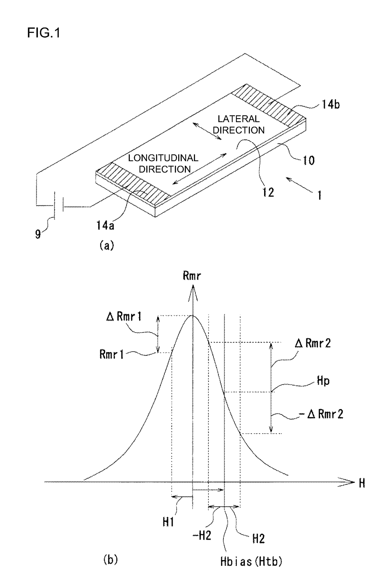
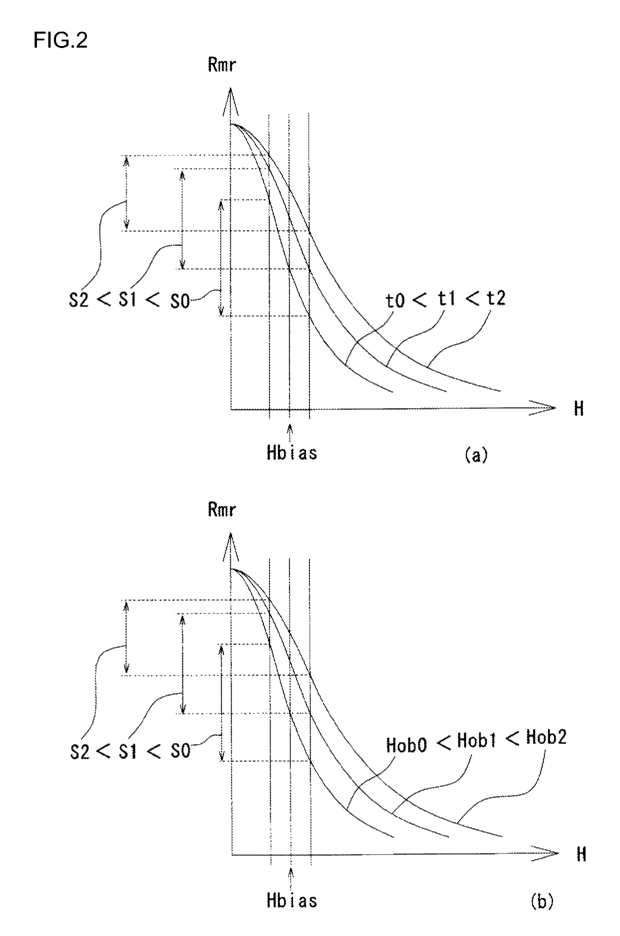
The present invention is about a sensor element that has a longitudinal bias magnetic field to suppress the magnetoresistance effect. However, the longitudinal bias magnetic field decreases with temperature, which decreases the sensitivity. The sensor element also has an effect from the magnetic film and the longitudinal bias magnetic field, which cancel each other out, resulting in a smaller change in sensitivity due to temperature. Additionally, the sensor element can be utilized with an oblique bias magnetic field to increase impedance, simplify the making process, and regulate sensitivity. The magnetic sensor and electric power measuring device can maintain accuracy and reliability, even in harsh temperature change.

Problems solved by technology

Meanwhile, as the usage expands, there is a possibility that an intended use environment is a harsh environment.

Method used


Image

  • Sensor element with temperature compensating function, and magnetic sensor and electric power measuring device which use same
  • Sensor element with temperature compensating function, and magnetic sensor and electric power measuring device which use same
  • Sensor element with temperature compensating function, and magnetic sensor and electric power measuring device which use same

Examples


embodiment 1

[0072]Next, with reference to FIG. 4, the configuration of a magnetic sensor with the temperature compensating function based on the principle will be shown. FIG. 4(a) shows the configuration of a magnetic sensor 2 with the temperature compensating function, and FIG. 4(b) shows an assembly diagram of a sensor element 13. The magnetic sensor 2 with the temperature compensating function includes the strip-shaped magnetic film 12 formed on the substrate 10, the electrodes 14a, 14b provided at both ends of the magnetic film 12, a current source 16 to apply an electric current between the electrodes 14a, 14b, a lateral bias magnetic field addition magnet 18, a longitudinal bias magnetic field addition magnet 20, and a voltmeter 22 to measure the voltage between the electrodes 14a, 14b.

[0073]The magnetic film 12 may be formed on the substrate 10 of glass, ceramics or the like. The material is not particularly limited, if the material exerts the magnetoresistance effect. The size can be a...

embodiment 2

[0088]FIG. 5 shows the configuration of a magnetic sensor 3 with the temperature compensating function according to the present embodiment. For the same parts as the magnetic sensor 2 with the temperature compensating function shown in Embodiment 1, the same reference characters are assigned, and the descriptions are omitted. In the magnetic sensor 3 with the temperature compensating function, the lateral bias magnetic field addition magnet 18 is configured by a pattern of an electric conductor 24 on the magnetic film 12.

[0089]On the magnetic film 12, a stripe pattern of the electric conductor 24 is formed between the electrodes 14a, 14b. For the electric conductor 24, similarly to the electrodes 14a, 14b, a material having a higher electric conductivity than that of the magnetic film 12 is used. The electric current flowing between the electrodes 14a, 14b flows through the intervals of the stripe-shaped electric conductor 24, across the shortest distance, and therefore, the angle o...

embodiment 3

[0100]In Embodiments 1 and 2, the configurations in which the temperature characteristic of the longitudinal bias magnetic field addition magnet 20 is made higher than the temperature characteristic of the lateral bias magnetic field addition magnet 18 and thereby the temperature characteristic of the sensor element 13 is kept constant as a whole have been described. This is a technical idea in which the temperature characteristic of the magnetic film 12 and the temperature characteristic of the longitudinal bias magnetic field addition magnet 20 cancel each other out. The sensor element 13 according to the present invention is not limited to this, and may be configured such that the temperature characteristic of the magnetic film 12 and the temperature characteristics of the longitudinal bias magnetic field addition magnet 20 and lateral bias magnetic field addition magnet 18 cancel each other out.

[0101]FIG. 7 shows the principle. FIG. 7 shows a graph of the magnetoresistance effec...


PUM


Abstract

A magnetoresistance effect type magnetic sensor has a problem in that the increase in the surrounding temperature decreases the magnetic characteristic of a magnetic film itself and thereby decreases the sensitivity of the sensor. A sensor element includes: a magnetic film having magnetoresistance effect; a pair of electrodes for applying an electric current to the magnetic film, the pair of electrodes being opposed across the magnetic film; a longitudinal bias magnetic field addition magnet to generate a first bias magnetic field in an opposing direction of the electrodes; and a lateral bias magnetic field addition magnet to generate a second bias magnetic field in an orthogonal direction to the longitudinal bias magnetic field addition magnet, in which a temperature characteristic of the longitudinal bias magnetic field addition magnet is higher than a temperature characteristic of the lateral bias magnetic field addition magnet.

Description

CROSS REFERENCE TO RELATED APPLICATIONS[0001]This application is a National Phase Entry of International Application No. PCT / JP2014 / 001905, filed Apr. 1, 2014, which claims priority to Japanese Application No. 2013-076469, filed Apr. 1, 2013. Each of the above-referenced patent applications is incorporated by reference in its entirety.TECHNICAL FIELD[0002]The present invention relates to a sensor element to which a temperature compensating function is added, and a magnetic sensor and an electric power measuring device which use same.BACKGROUND ART[0003]It is predicted that the usage of compact magnetic sensors will expand increasingly. Particularly, it is thought that an electric power measuring device is an essential device in the case of intending to utilize electric energy from fossil fuel. Patent Literature 1 discloses an electric power measuring device that connects a magnetic sensor and a sensor resistance in series, installs the magnetic sensor and the sensor resistance so as...

Claims


Application Information

Patent Timeline
Patent Type & Authority Patents(United States)
IPC IPC(8): G01R21/08G01R33/09H01L43/08
CPCG01R21/08G01R33/093H01L43/08H10N50/10
Inventor TSUJIMOTO, HIROAKI
Owner SIRC CO LTD
Learn More