Sensor element with temperature compensating function, and magnetic sensor and electric power measuring device which use same
a technology of temperature compensation and sensor element, applied in the direction of measurement device, magnetic measurement, instruments, etc., can solve the problem of harsh environment of intended use environment, and achieve the effect of maintaining sensitivity, reducing longitudinal bias magnetic field, and reducing sensitivity
- Summary
- Abstract
- Description
- Claims
- Application Information
AI Technical Summary
Benefits of technology
Problems solved by technology
Method used
Image
Examples
embodiment 1
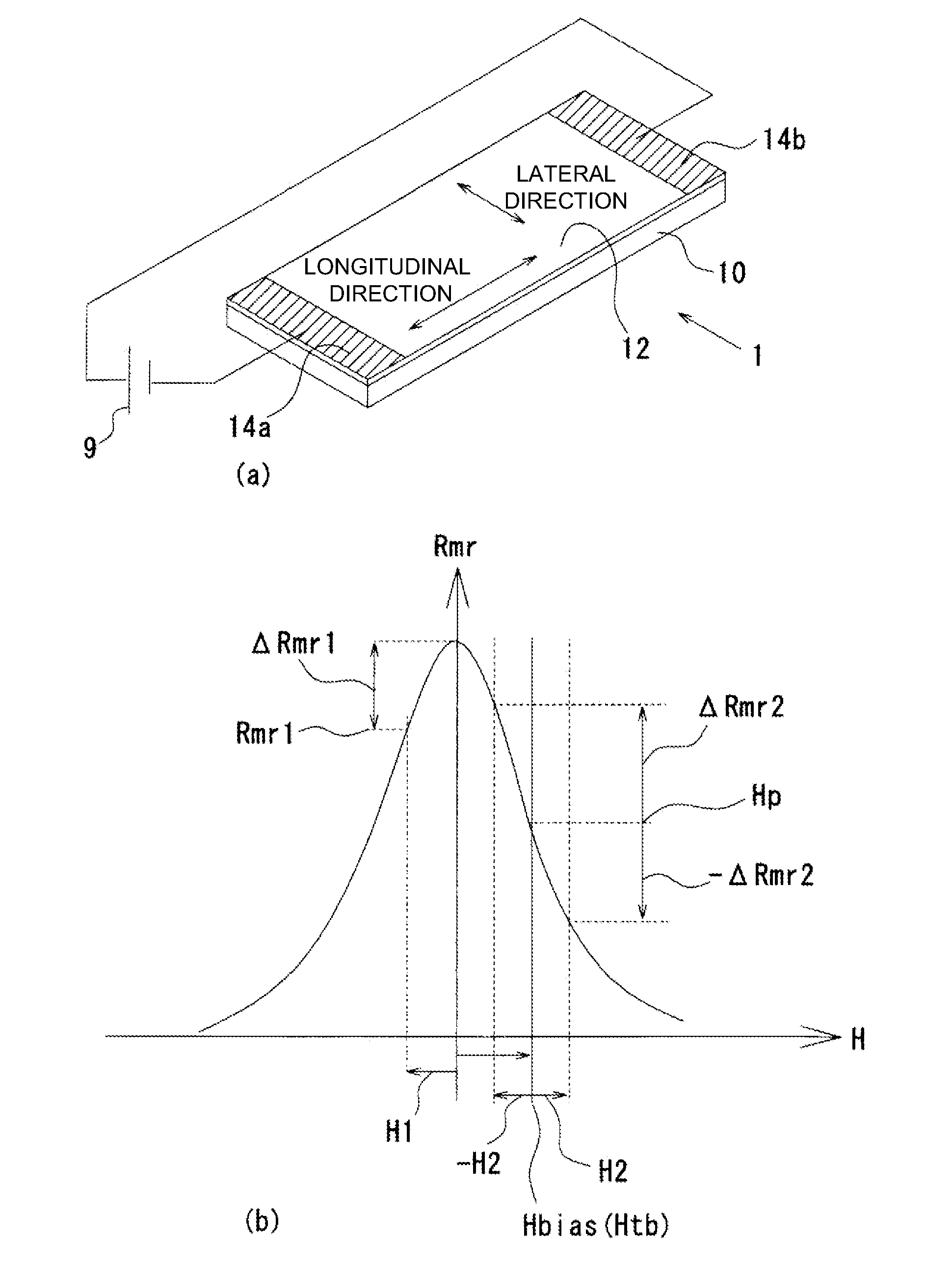
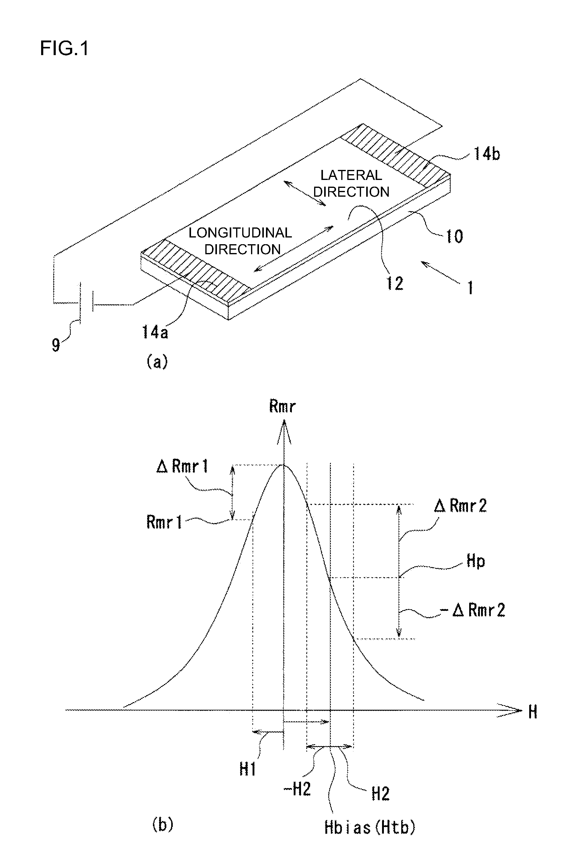
[0071]Next, with reference to FIG. 4, the configuration of a magnetic sensor with the temperature compensating function based on the principle will be shown. FIG. 4(a) shows the configuration of a magnetic sensor 2 with the temperature compensating function, and FIG. 4(b) shows an assembly diagram of a sensor element 13. The magnetic sensor 2 with the temperature compensating function includes the strip-shaped magnetic film 12 formed on the substrate 10, the electrodes 14a, 14b provided at both ends of the magnetic film 12, a current source 16 to apply an electric current between the electrodes 14a, 14b, a lateral bias magnetic field addition magnet 18, a longitudinal bias magnetic field addition magnet 20, and a voltmeter 22 to measure the voltage between the electrodes 14a, 14b.
[0072]The magnetic film 12 may be formed on the substrate 10 of glass, ceramics or the like. The material is not particularly limited, if the material exerts the magnetoresistance effect. The size can be a...
embodiment 2
[0087]FIG. 5 shows the configuration of a magnetic sensor 3 with the temperature compensating function according to the present embodiment. For the same parts as the magnetic sensor 2 with the temperature compensating function shown in Embodiment 1, the same reference characters are assigned, and the descriptions are omitted. In the magnetic sensor 3 with the temperature compensating function, the lateral bias magnetic field addition magnet 18 is configured by a pattern of an electric conductor 24 on the magnetic film 12.
[0088]On the magnetic film 12, a stripe pattern of the electric conductor 24 is formed between the electrodes 14a, 14b. For the electric conductor 24, similarly to the electrodes 14a, 14b, a material having a higher electric conductivity than that of the magnetic film 12 is used. The electric current flowing between the electrodes 14a, 14b flows through the intervals of the stripe-shaped electric conductor 24, across the shortest distance, and therefore, the angle o...
embodiment 3
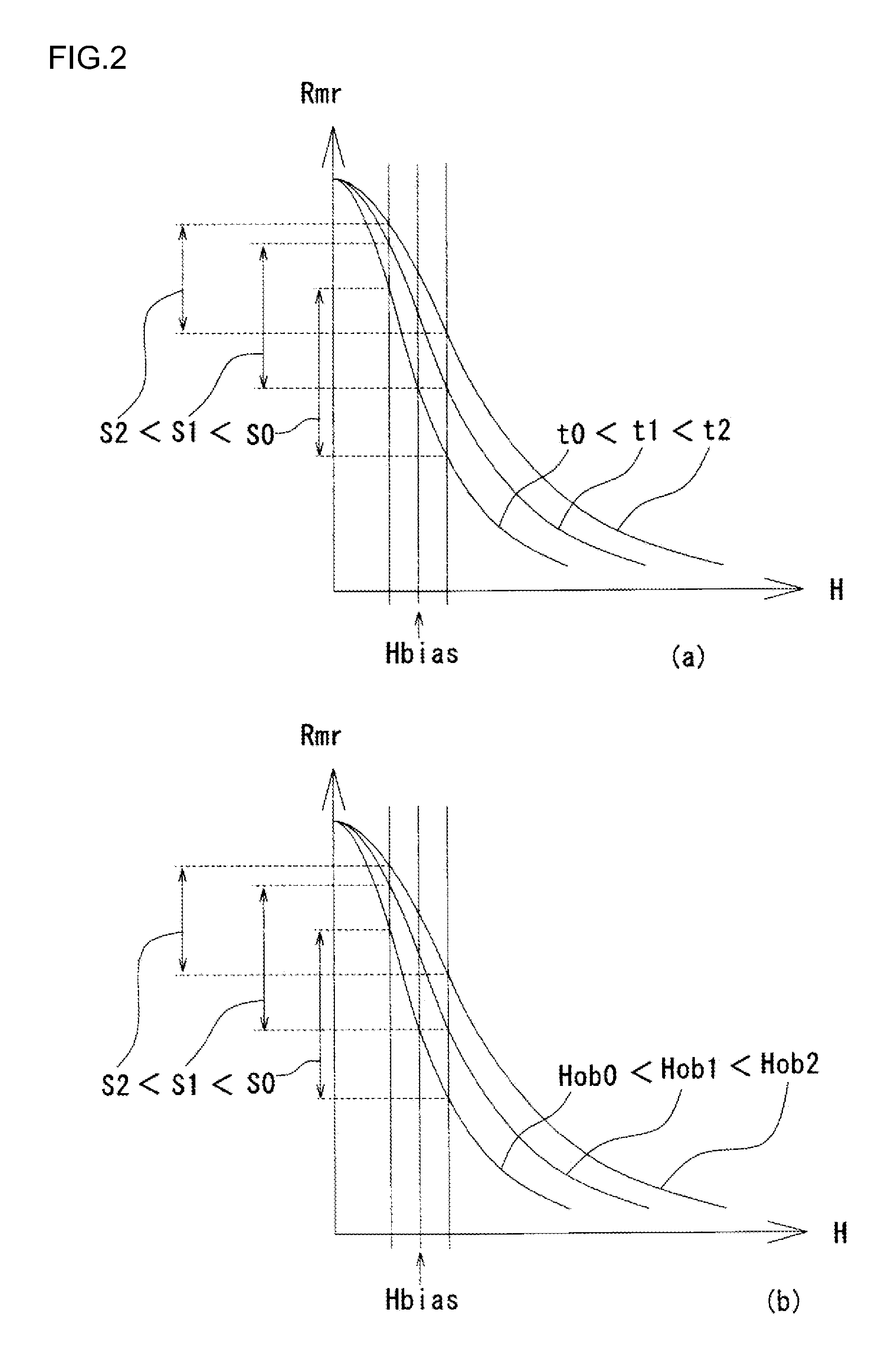
[0099]In Embodiments 1 and 2, the configurations in which the temperature characteristic of the longitudinal bias magnetic field addition magnet 20 is made higher than the temperature characteristic of the lateral bias magnetic field addition magnet 18 and thereby the temperature characteristic of the sensor element 13 is kept constant as a whole have been described. This is a technical idea in which the temperature characteristic of the magnetic film 12 and the temperature characteristic of the longitudinal bias magnetic field addition magnet 20 cancel each other out. The sensor element 13 according to the present invention is not limited to this, and may be configured such that the temperature characteristic of the magnetic film 12 and the temperature characteristics of the longitudinal bias magnetic field addition magnet 20 and lateral bias magnetic field addition magnet 18 cancel each other out.
[0100]FIG. 7 shows the principle. FIG. 7 shows a graph of the magnetoresistance effec...
PUM
 Abstract
Description
Claims
Application Information
 - R&D
- Intellectual Property
- Life Sciences
- Materials
- Tech Scout
- Unparalleled Data Quality
- Higher Quality Content
- 60% Fewer Hallucinations
Browse by: Latest US Patents, China's latest patents, Technical Efficacy Thesaurus, Application Domain, Technology Topic, Popular Technical Reports.
© 2025 PatSnap. All rights reserved.Legal|Privacy policy|Modern Slavery Act Transparency Statement|Sitemap|About US| Contact US: help@patsnap.com


