Check patentability & draft patents in minutes with Patsnap Eureka AI!

Methods for cleaning precipitators

a precipitator and cleaning technology, applied in the field of power generation, can solve the problems of system outage, difficult to remove particulate matter that has adhered to the components, and accumulation of particles on the collecting surfa

Inactive Publication Date: 2017-09-05
US NITRO BLASTING & ENVIRONMENTAL LLC
View PDF26 Cites 0 Cited by
  • Summary
  • Abstract
  • Description
  • Claims
  • Application Information

AI Technical Summary

Benefits of technology

Enables efficient cleaning of precipitators in operation, maintaining system efficiency and reducing the need for premature replacement of components, thereby minimizing downtime and operational costs.

Problems solved by technology

However, regardless of the type of precipitator used, particulate may accumulate on the collecting surfaces over time.
It may be difficult to remove particulate matter that has adhered to the components of the precipitator, and quite often, to clean such components effectively, the unit must be removed from service.
Because known industrial systems do not commonly own redundant precipitators, removing the precipitator to clean it may require a system outage before a time-consuming and costly cleaning can be performed.

Method used


Image

  • Methods for cleaning precipitators
  • Methods for cleaning precipitators
  • Methods for cleaning precipitators

Examples


Embodiment Construction

[0011]The following detailed description illustrates methods for cleaning precipitators by way of example and not by way of limitation. The description enables one of ordinary skill in the art to practice the methods, and the description describes several embodiments of the methods, including what is presently believed to be the best mode of carrying them out. The methods are described herein as being applied to a preferred embodiment, namely a precipitator of an industrial system. However, it is contemplated that the methods have general application to cleaning a broad range of components in a broad range of systems aside from precipitators in industrial systems.

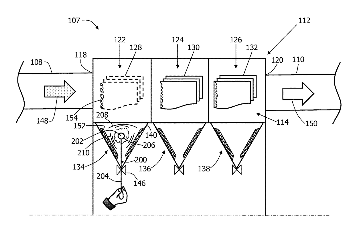
[0012]FIG. 1 is a schematic illustration of an exemplary industrial system 100. In the exemplary embodiment, industrial system 100 is a power plant (e.g., a coal-fired power plant) that includes a fuel-burning apparatus 102 (e.g., a boiler) that generates a gaseous byproduct (i.e., an exhaust flow). Industrial system 100 al...


PUM


Abstract

A method for cleaning a precipitator having a hopper defining an interior space and a drain valve is provided. The method includes inserting an explosive device into the interior space defined within the hopper via the drain valve, while the precipitator remains on-line. The method also includes detonating the explosive device to cause particulate matter contained therein to loosen for removal through the drain valve.

Description

BACKGROUND[0001]The field of this disclosure relates generally to power generation and, more particularly, to methods for cleaning a precipitator of an industrial system.[0002]During operation, many known industrial systems such as, for example, fuel-burning systems, generate a gaseous byproduct or exhaust gases that are eventually channeled towards the atmosphere. Known exhaust gases contain combustion products including, but not limited to, carbon, fly ash, carbon monoxide, water, hydrogen, nitrogen, sulfur, chlorine, arsenic, selenium, and / or mercury. It is generally required that particulate matter suspended in the gaseous byproduct be removed before the gaseous byproduct is exhausted into the ambient.[0003]Emissions from industrial systems are subject to government regulation. As such, at least some known industrial systems include a pollution control system that facilitates reducing particulate matter and / or constituents from the exhaust gas flow prior to the exhaust gases bei...

Claims


Application Information

Patent Timeline
Patent Type & Authority Patents(United States)
IPC IPC(8): B03C3/74B03C3/76B01D53/32B08B7/00
CPCB03C3/74B01D53/32B03C3/76B08B7/0007B03C2201/32
Inventor WARREN, BRIAN P.WARREN, PHILIP F.MASSIE, LARRY R.
Owner US NITRO BLASTING & ENVIRONMENTAL LLC
Features
  • R&D
  • Intellectual Property
  • Life Sciences
  • Materials
  • Tech Scout
  • Unparalleled Data Quality
  • Higher Quality Content
  • 60% Fewer Hallucinations
Learn More