
Interactive lighting effect portable light illuminating devices and system thereof

a portable light and interactive technology, applied in the field of wireless interactive lighting effect portable light illuminating devices, can solve the problems of inability to adapt to inability to properly present actual real-time scores in sporting events, and inability to handle new improvisational light control changes. , to achieve the effect of improving the range of rf data transmission, improving scalability and expansion, and improving the ability to assign zones and zones more diversely

Active Publication Date: 2017-09-12
LUMIC TECH INC
View PDF19 Cites 6 Cited by
  • Summary
  • Abstract
  • Description
  • Claims
  • Application Information

AI Technical Summary

Benefits of technology

[0009]The present invention provides the interactive lighting effect portable light illuminating device having more than one light source, the controller is configured to cause the light sources selectively to emit light in accordance with a received illuminating color and zone assignment sequence data file for providing continuous automated and coordinated lighting effect.
[0014]The present invention provides two or more interactive lighting effect portable light illuminating devices are capable of receiving the same set of illuminating color and zone assignment data to cause the light sources selectively to be illuminating in accordance with the same illuminating color and zone assignment data.
[0023]Some of the advantages of the portable light illuminating devices equipped with LEDs or the interactive lighting effect portable light illuminating device configured to be operating in an integrated and coordinated illuminating environment to produce continuous dynamic visual effects on a mass scale using the interactive lighting effect control system of present invention, in which the portable light illuminating devices equipped with LEDs can be illuminating LED wristbands and / or handheld LED glow sticks, include at least the following: (a) none of pre-programmed LED illumination light control sequences, indexed by corresponding activation codes, need to be stored inside the memory thereof; (b) achieving a lighting performance for an entire venue event having plenty of sophisticated or intricate illuminating sequences would only a small amount of zone code multi-level assignment hierarchical table data to be pre-stored in the memory for implementing various surprise or improvisational lighting changes; (c) any lighting or illumination change can be integrated on the fly on top of or manually overriding the pre-programmed LED illumination sequences at any time using a DMX lighting controller. In other words, any desired lighting change with various improvisational zone code behaviors need not be already pre-programmed into each of the memory of the illuminating LED wristbands and handheld LED glow sticks ahead of time, for such lighting change to be properly implemented during the venue event. (pairing of light control sequence action and corresponding activation code are not needed at all). Therefore, when a surprise guest arrives at the stage of a concert event or an actual real-time score taking place in a sporting event can be effectively incorporated seamlessly transition into on-going illumination sequences among a large number of the illuminating LED wristbands and handheld LED glow sticks; (d) subtle color changes during a choreographed lighting control sequence would carry along the same amount of data overhead for the memory of each illuminating LED wristbands and handheld LED glow sticks, because each subtle color change is entered as a RF data burst transmission comprising a set of illuminating color and zone assignment data in the form of a data packet to be broadcasted to all illuminating LED wristbands and handheld LED glow sticks; (e) having improved and more diverse zone assignment capability using more than one nested hierarchical zone codes for the assignment of the zone regions; (f) allows for improved scalability and expansion for usage on a larger scale through adding one or more repeaters for increasing the coverage range of the RF data transmission.

Problems solved by technology

Some of the limitations of the existing related technologies adopted by the illuminating LED wristbands and handheld LED glow sticks are that all of the pre-programmed LED illumination light control sequences, indexed by corresponding activation codes, have to be stored ahead of time before each venue event inside the memory thereof, which means that, in order to achieve a lighting performance for an entire venue event having more sophisticated or intricate lighting or illuminating sequences would certainly require to store a huge amount of light control data in the memory for matching against the huge number of necessary lighting changes.
Meanwhile, the existing lighting control methods for the illuminating LED wristbands and handheld LED glow sticks do not allow for any surprise, improvisational or spur of the moment lighting changes to be integrated on top of the pre-programmed LED illumination sequences.
In other words, any single change must be already pre-programmed into each of the memory of the illuminating LED wristbands and handheld LED glow sticks ahead of time, for such lighting change to be properly implemented during the venue event; otherwise, the illuminating LED wristbands and handheld LED glow sticks would not be able to handle any new improvisational light control change without having the necessary data in the memory (pairing of light control sequence action and corresponding activation code).
Therefore, as examples, a name of a surprise guest arriving to the stage of a concert event or an actual real-time score taking place in a sporting event cannot be choreographed to be presented into proper illumination sequences among a sea of the illuminating LED wristbands and handheld LED glow sticks.

Method used


Image

  • Interactive lighting effect portable light illuminating devices and system thereof
  • Interactive lighting effect portable light illuminating devices and system thereof
  • Interactive lighting effect portable light illuminating devices and system thereof

Examples


Embodiment Construction

[0043]The present invention will now be described more specifically with reference to the following embodiments. It is to be noted that the following descriptions of the embodiments of this invention are presented herein for purpose of illustration and description only. It is not intended to be exhaustive or to be limited to the precise form disclosed.

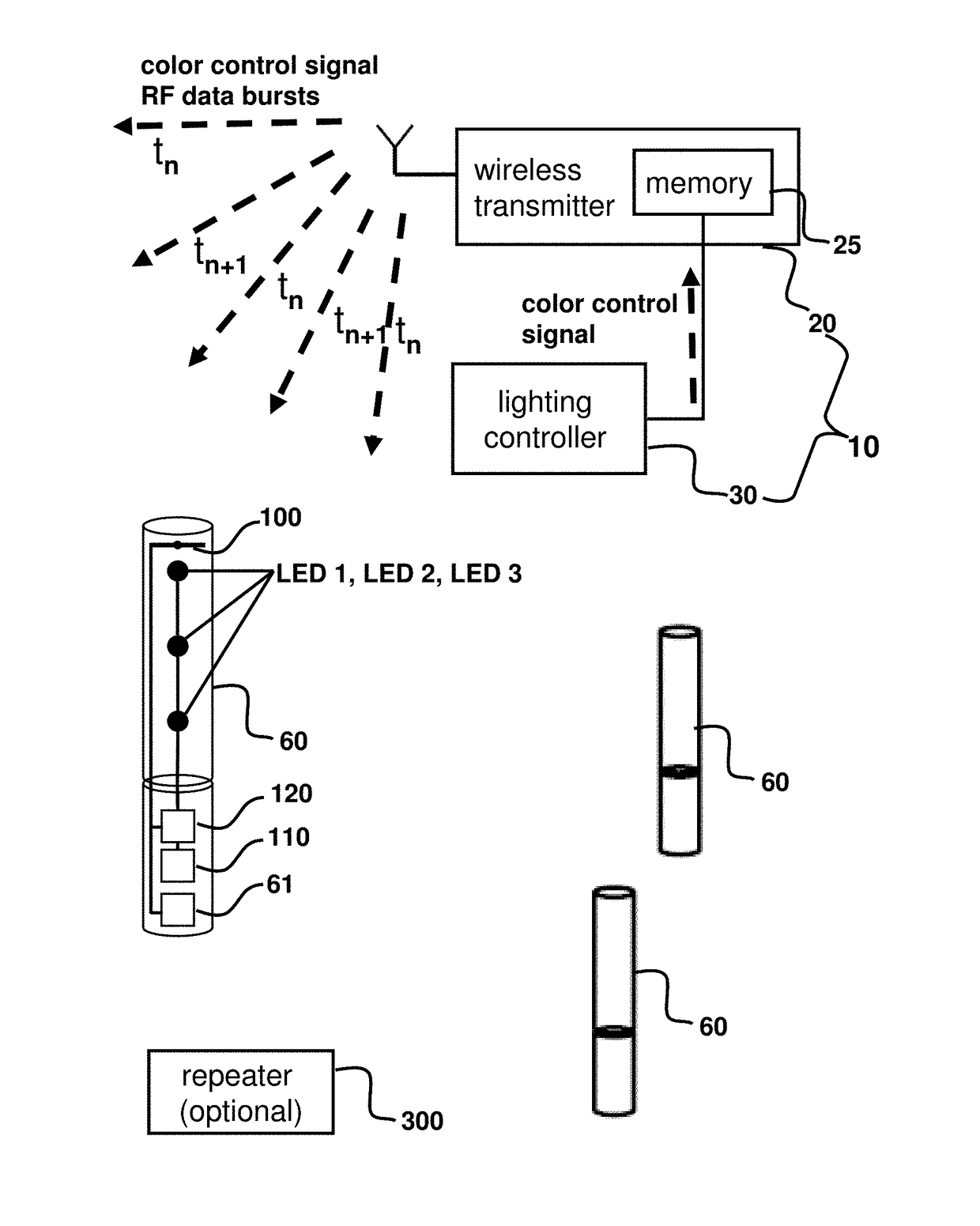
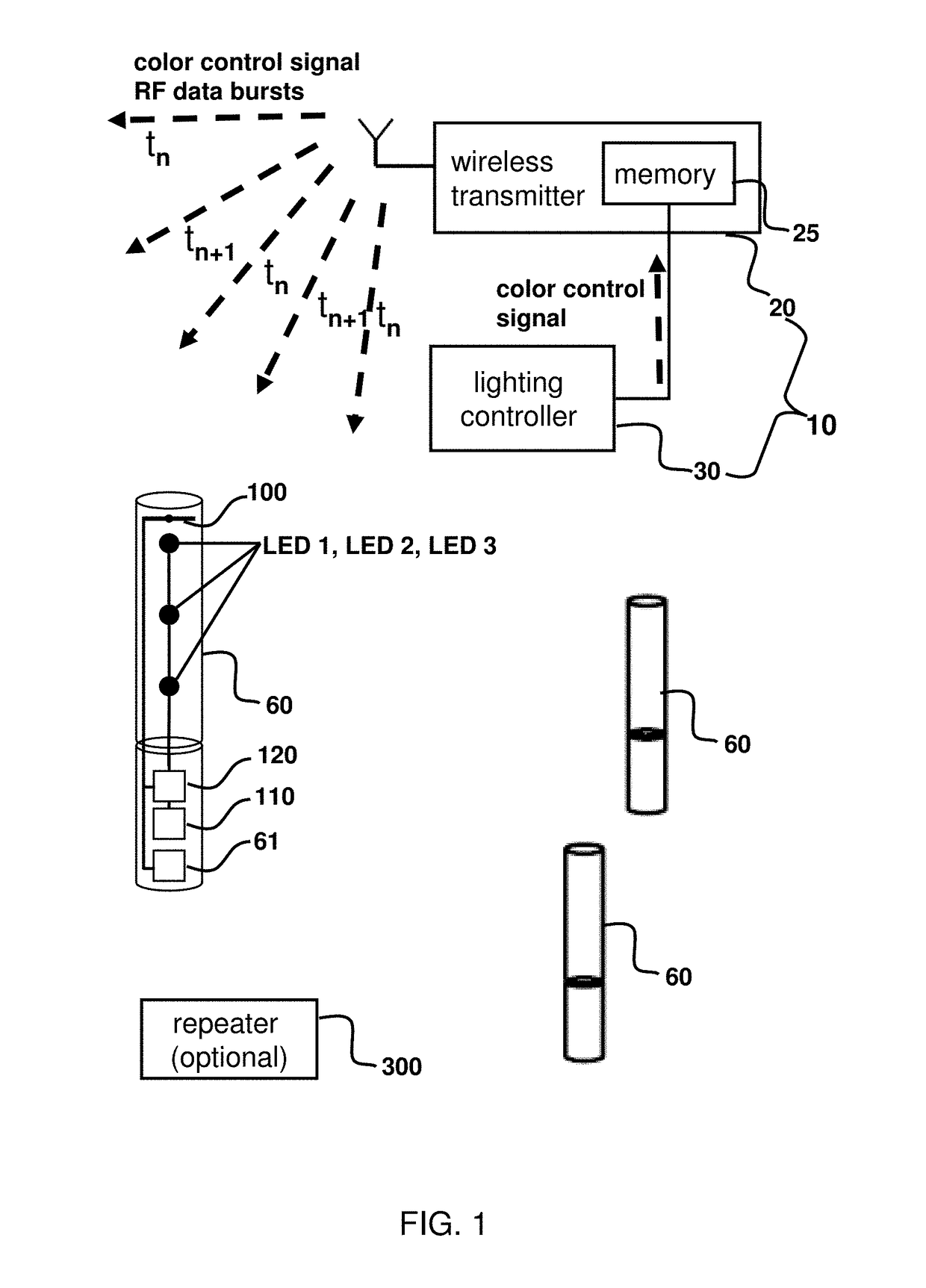
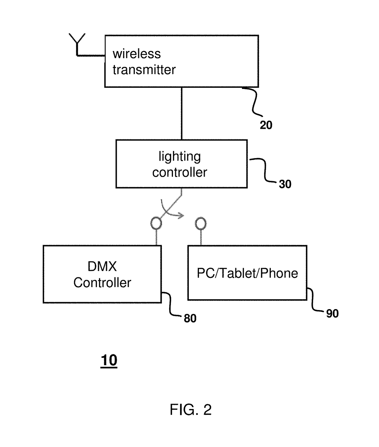
[0044]As shown in FIGS. 1 and 2 together, an interactive lighting effect control system 10 configured and adapted for use together with a plurality of interactive lighting effect portable light illuminating devices 60 in accordance with an embodiment of present invention is shown. The interactive lighting effect control system 10 includes a wireless transmitter 20 comprising a memory 25 and at least one lighting controller 30. The wireless transmitter 20 can be formed or provided by an RF transmitter chip together with other accessory electronic components, such as, for example, Texas Instrument model number CC2541 or CC2500 RF transce...


PUM


Abstract

Portable light illuminating device with RF receiver along with interactive lighting effect control system with RF transmitter via wireless data transmissions are provided. RF data burst are captured to illuminate LEDs disposed in portable light illuminating device selectively in accordance with illuminating color and zone assignment data and matching nested hierarchical zone codes, which can be assigned for seating location within one seating zone, several seating zones, and segment within one seating zone. Improvisational manual illuminating color control change for any zone assignment for color control signal can be generated and converted to set of RGB color codes as well as color control signals extracted from sound track using color show control software from PC / laptop can be encoded and sequenced using lighting controller to be transmitted to wireless RF transmitter for broadcasting as data burst. DMX controller and PC / Laptop can also be part of the interactive lighting effect control system.

Description

FIELD OF THE INVENTION[0001]The present invention generally relates to a wireless interactive lighting effect portable light illuminating device and, more particularly, to one or more portable light illuminating devices equipped with LEDs configured to be operating in an integrated and coordinated wireless illuminating environment using an interactive lighting effect control system to produce continuous dynamic lighting or illuminating effects on a mass scale.BACKGROUND OF THE INVENTION[0002]Wristbands, containing a message or logo and made of silicone, have become popular as reliable and effective authorization device for entry access into various venue events, such as a music concert or sporting event. The wristband typically includes a serial number, a RFID ID tag, or other unique identification markings (such as a barcode) that can be scanned to authenticate the wristband and permits the entry of the wristband wearer through a security checkpoint or a main gate for the venue eve...

Claims


Application Information

Patent Timeline
Patent Type & Authority Patents(United States)
IPC IPC(8): H05B37/02H05B33/08H05B44/00
CPCH05B37/0272H05B33/0845H05B33/0863H05B45/00H05B45/20H05B47/19Y02B20/30H05B45/10
Inventor HUANG, TA-WEILU, YING-KO
Owner LUMIC TECH INC
Learn More