Power system for a working machine

a power system and working machine technology, applied in fluid hybrid vehicles, fluid gearings, vehicles, etc., can solve the problems of limited maximum flow of hydraulic machines, small flow demand of hydraulics, and large power loss over torque converters, so as to increase the pressure level of accumulators and improve recuperation efficiency

Active Publication Date: 2017-09-19
VOLVO CONSTR EQUIP AB
View PDF15 Cites 11 Cited by
  • Summary
  • Abstract
  • Description
  • Claims
  • Application Information

AI Technical Summary

Benefits of technology

[0030]In one embodiment of the invention, the hydraulic variator unit may comprise a first hydraulic machine and a second hydraulic machine, and at least one of the first hydraulic machine and the second hydraulic machine is hydraulically connected to the work hydraulic circuit. The chosen design of the mechanical gearbox connected to variator the hydraulic machines sets the requirements on which type of hydraulic machines that should be used inside the variator unit. However, to get the full advantage of the invention it is recommended that hydraulic machines are capable of reversed power flow transformation (in order to support recuperation of energy). This implies the use of a hydraulic machine that can operate in at least in two quadrants, meaning both as a pump and as a motor. The practical way to solve this is to adopt hydraulic machines that allow a reversed flow direction (through negative displacement capability). This type of machine is commonly referred to as “open circuit, over-center machines” which is commonly used in “secondary control system” applications. However the motoring capability can also be achieved with a machine only capable of unidirectional flow capability, but in this case the reversed power flow must be achieved through switching valves, changing side of pressurization of the hydraulic machines. For this solution another type of hydraulic machine is needed, since there is no longer any predetermined high and low pressure side. This type of machine is commonly referred to as a closed-circuit hydraulic machine.
[0031]According to one embodiment of the invention, at least one of the first hydraulic machine and the second hydraulic machine may be hydraulically connected to the hydraulic energy storage. In a conventional system, if the same hydraulic energy storage is used by the driveline and the work hydraulics, where the work hydraulics is powered by a power take-off and a separate hydraulic machine, there may be problems as the hydraulic machine of the work hydraulic must be of significant size to be able to be handle powers coming back from the propulsion system. According to the present embodiment, one or both of the hydraulic machines can be used to transfer power to both the driveline for propulsion and to the work hydraulics, thereby making the power limitation encountered in prior art solutions less of a problem. Furthermore, fewer power transformations are required when recuperating energy from the propulsion system compared to prior art solutions. Hence, higher recuperation efficiency is expected.
[0032]According to one embodiment of the invention, the power system ma further comprise a control unit configured to maintain a pressure level of the hydraulic energy storage within a first predetermined range. The control unit can he active to control the hydraulic flow in the system such that a pressure level of the hydraulic accumulator is maintained above a predetermined minimum value and below a predetermined maximum value. For example, if the pressure level of the hydraulic accumulator is approaching its minimum value, the engine can be activated to provide hydraulic flow via the variator unit to the accumulator so that the pressure level of the accumulator is increased. Furthermore, if the pressure level of the hydraulic accumulator is below its maximum value, and if the power system is in a mode where energy may be recuperated, either from the propulsion of from the work hydraulics, the control unit may advantageously redirect recuperated energy to the hydraulic accumulator. The control unit may be any unit suitable for controlling functions in a hydraulic system such as a microprocessor or the like configured to control for example the variator unit or a separate accumulator charging system to control pressure levels in one or more hydraulic accumulators.
[0033]In one embodiment of the invention, the power system may further comprise a second hydraulic energy storage hydraulically connected to the hydraulic variator unit and to the work hydraulic circuit. The second accumulator could also advantageously be connected to the low pressure side of the work hydraulic system. The main reason to use a low pressure accumulator is to maintain a sufficiently large pressure on the suction side of any reciprocating hydraulic element, such as a pump or cylinder in order to avoid cavitation. If a second accumulator is not used in the system, the normal solution is instead to use a hydraulic tank pressurized by atmospheric pressure.
[0034]Furthermore, the control unit may advantageously be configured to maintain a pressure level of the second hydraulic energy storage within a second predetermined range different from the first predetermined range. By providing hydraulic accumulators having different pressure levels, different components of the work hydraulic circuit requiring different hydraulic pressure may be powered by different hydraulic accumulators.
[0035]According to one embodiment of the invention, the variator unit may advantageously be input coupled. That the hydraulic machine is input coupled means that one hydraulic machine of the variator unit is coupled to the input shaft of the gear box.

Problems solved by technology

This means that the maximum flow of the hydraulic machine is limited by the engine speed and so is the transmission torque.
In some cases high hydraulic flow is needed, but the torque request on the propulsion is low, a high engine speed is needed to satisfy the hydraulic system, which will lead to big power losses over the torque converter since the operator will stop the machine from going forward by applying the friction brakes, and heat will be generated over the torque converter.
Also the other way around can be a problem; the propulsion system requires a high engine rpm to perform the commanded torque output, while the hydraulics only has a very small flow demand.
This situation will also cause problems, but this time power losses occur in the hydraulic system, since the hydraulic machine must operate at partial displacement, where the efficiency is lower compared to when operating, at full flow.
Other issues in the motion systems of most construction machines today is that kinetic energy stored in the mass of a moving machine is not recovered when the machine is decelerated, nor is the potential energy of an elevated load recovered when the load is lowered.
Today this kinetic and potential energy is generally wasted as heat over friction brakes and hydraulic resistances.
However the motoring capability can also be achieved with a machine only capable of unidirectional flow capability, but in this case the reversed power flow must be achieved through switching valves, changing side of pressurization of the hydraulic machines.
In a conventional system, if the same hydraulic energy storage is used by the driveline and the work hydraulics, where the work hydraulics is powered by a power take-off and a separate hydraulic machine, there may be problems as the hydraulic machine of the work hydraulic must be of significant size to be able to be handle powers coming back from the propulsion system.

Method used


Image

  • Power system for a working machine
  • Power system for a working machine
  • Power system for a working machine

Examples


Embodiment Construction

[0061]In the present detailed description, various embodiments of a power system according to the present invention are mainly discussed with reference to a power system for a wheel loader. It should however be noted that this by no means limits the scope of the present invention which is equally applicable to power systems in other types of working machine or vehicle

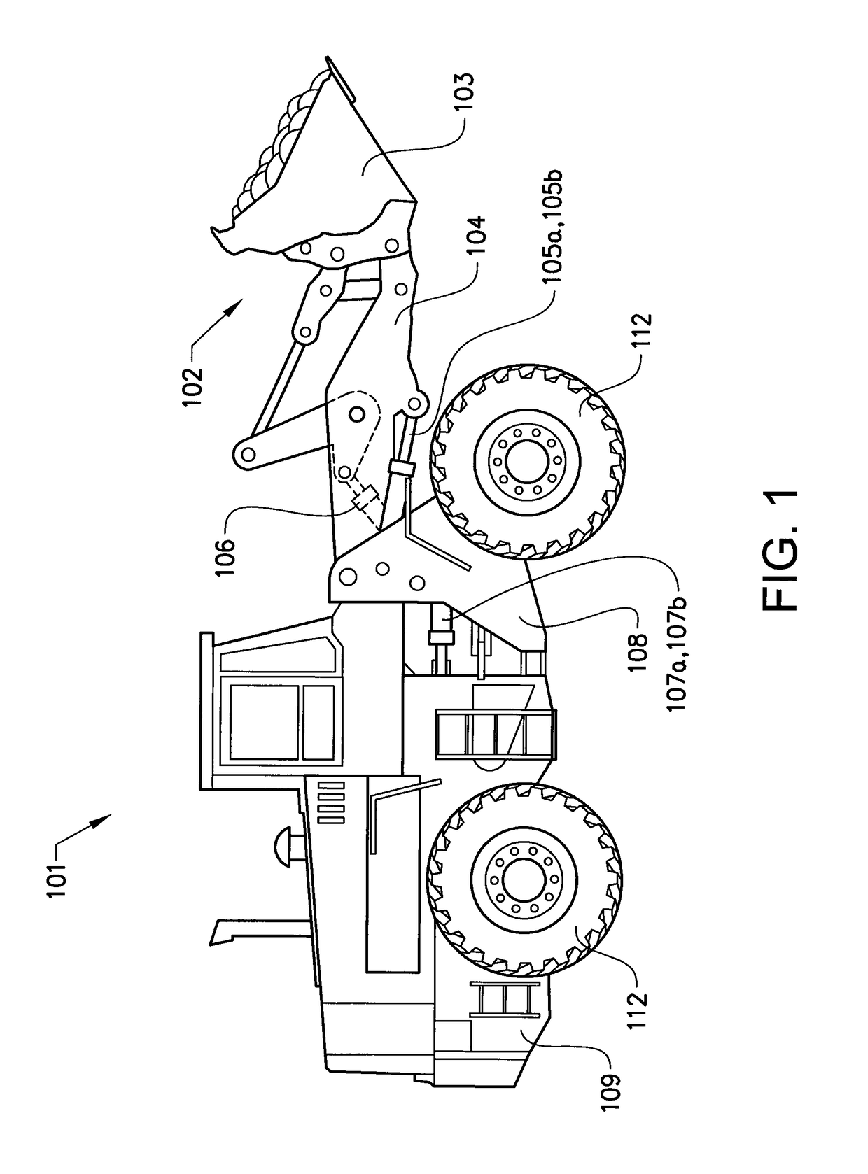
[0062]Reference is now made to FIG. 1, illustrating a working machine 101, here in the form of a wheel loader having an implement 102. The term “implement” is intended to comprise any kind of tool using hydraulics, such as a bucket, a fork or a gripping, tool arranged on a wheel loader, or a container arranged on an articulated hauler. The implement illustrated comprises a bucket 103 which is arranged on an arm unit 104 for lifting and lowering the bucket 103, and further the bucket 103 can be tilted or pivoted relative to the arm unit 104. The wheel loader 101 is provided with a hydraulic system for example to lift and...


PUM


Abstract

A power system for a working machine includes a transmission for driving the working machine, the transmission including a continuously variable gear box having a gear unit and a hydraulic variator unit; a work hydraulic circuit for controlling at least one hydraulic actuator of the working machine; wherein the hydraulic variator unit is hydraulically connected to the work hydraulic circuit to hydraulically transfer energy from the hydraulic variator unit to the work hydraulic circuit.

Description

BACKGROUND AND SUMMARY[0001]The invention relates to a power system and to a working machine comprising such a power system.[0002]The invention is applicable on working machines within the fields of industrial construction machines, in particular wheel loaders, articulated haulers and excavators. Although the invention will be described hereinafter with respect to a wheel loader, the invention is not restricted to this particular machine, but may also be used in other heavy working machines, such as dump trucks, or other construction equipment.[0003]A working machine is typically provided with an internal combustion engine for propulsion of the working machine via a gear box, and for providing power w one or more auxiliary hydraulic systems of the working machine. Such hydraulic systems can include steering and one or more working hydraulic circuits of a working machine.[0004]One or more hydraulic pumps can be used to provide hydraulic power to the one or more hydraulic systems of t...

Claims


Application Information

Patent Timeline
Patent Type & Authority Patents(United States)
IPC IPC(8): F16D31/02B60K6/12F16H61/4078B60W10/30F15B11/17F15B21/14F15B21/08F15B13/06F15B11/16F16H47/04E02F9/20F16H61/4096E02F9/22F16H47/02
CPCE02F9/2217B60K6/12B60W10/30E02F9/202E02F9/2253E02F9/2267E02F9/2292E02F9/2296F15B11/16F15B11/17F15B13/06F15B21/08F15B21/14F16H47/02F16H47/04F16H61/4078F16H61/4096F15B2211/255F15B2211/265F15B2211/40F15B2211/625F15B2211/63F15B2211/7058F16H2047/025Y02T10/6208Y02T10/76Y02T10/62Y02T10/60
Inventor HEYBROEK, KIMLARSSON, JONASPETTERSSON, KARLKRUS, PETTER
Owner VOLVO CONSTR EQUIP AB
Why Eureka
Try Eureka