Thermoelectric cooling module

a technology of thermal insulation and cooling module, which is applied in the direction of printed circuit aspects, electrical apparatus construction details, stacked spaced pcbs, etc., can solve the problems of large thermal resistance, difficult to cover and fix the copper plate to the surface of the ceramic plate, and complicated sintering mold manufacturing processes of the ceramic substrate. achieve excellent conductivity, good elasticity and tenacity

Active Publication Date: 2017-10-03
DELTA ELECTRONICS INC
View PDF13 Cites 3 Cited by
  • Summary
  • Abstract
  • Description
  • Claims
  • Application Information

AI Technical Summary

Benefits of technology

[0006]It is a primary objective of this disclosure to provide a thermoelectric cooling module using a circuit board to substitute the conventional ceramic plate, wherein the circuit board with circuits comes with good elasticity and tenacity, and the heat generated by a TED chip can be conducted to the outside directly through a first conducting member and a second conducting member, so that the thermoelectric cooling module has the features of excellent conductivity, structural strength and heat dissipation efficiency.

Problems solved by technology

However, the traditional thermoelectric cooling module has the following drawbacks: 1. The complicated sintering and mold manufacturing processes of the ceramic substrate consume much energy, and it is difficult to cover and fix the copper plate to the surface of the ceramic plate, and thus the copper plate may be separated from the ceramic plate easily.
The TED chip must conduct heat to the copper plate before the heat is conducted to the fins through the copper plate and the ceramic substrate, and thus the thermal resistance is large, and a quick thermal conduction cannot be achieved.
The flexibility of configuring the ceramic substrate and the copper plate is poor, and thus the serial connection, parallel connection, shape, and size cannot be adjusted flexibly, and the ceramic substrate is lack of tenacity, so that the ceramic substrate may be cracked, broken, or damaged by vibration and thermal shock easily.

Method used


Image

  • Thermoelectric cooling module
  • Thermoelectric cooling module
  • Thermoelectric cooling module

Examples


Embodiment Construction

[0012]The technical contents of this disclosure will become apparent with the detailed description of preferred embodiments accompanied with the illustration of related drawings as follows. It is intended that the embodiments and figures disclosed herein are to be considered illustrative rather than restrictive.

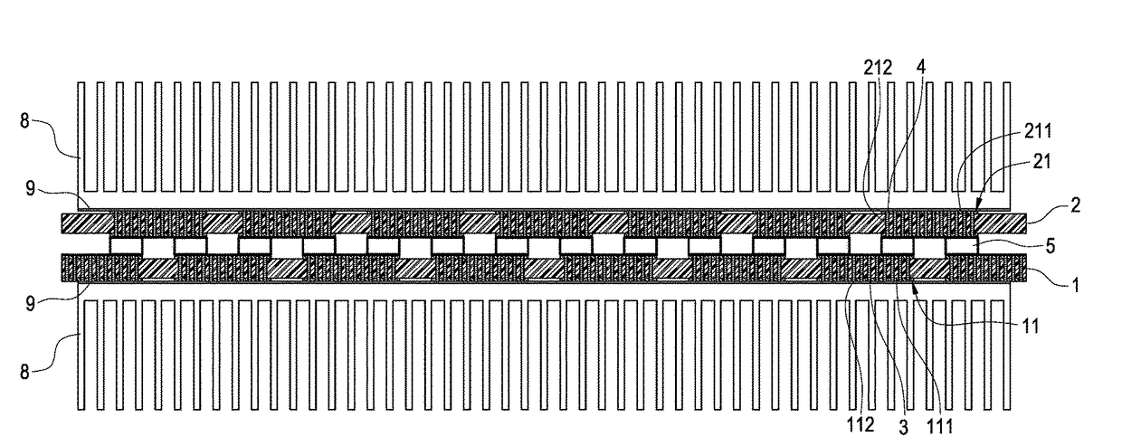
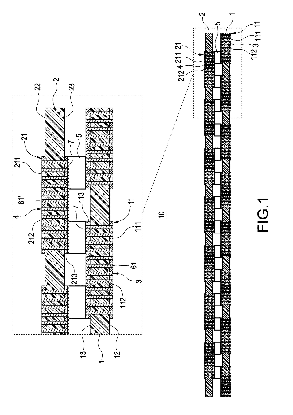
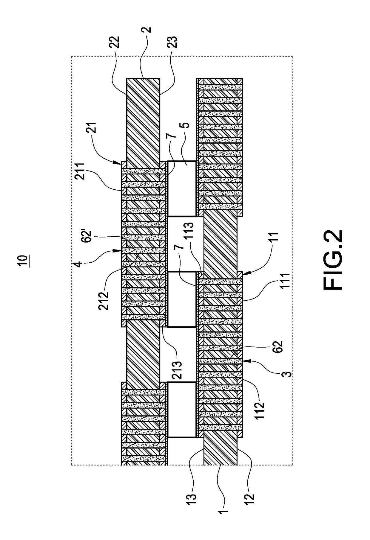
[0013]With reference to FIG. 1 for a thermoelectric cooling module of this disclosure, the thermoelectric cooling module 10 comprises a first circuit board 1, a second circuit board 2, a plurality of first conducting members 3, a plurality of second conducting members 4, and a plurality of TED chips 5.

[0014]The first circuit board 1 has a plurality of first circuit regions 11, and a plurality of first circuit regions 11 which are arranged apart with each other and in a front rear, left, and right matrix form, and each first circuit region 11 has a first conducting layer 111, a first circuit layer 113 and a plurality of first penetrating holes 112, and the first conducting lay...


PUM


Abstract

A thermoelectric cooling module includes a first circuit board, a second circuit board, first conducting members, second conducting members and TED chips. The first circuit board includes first circuit regions, each having a first conducting layer and first penetrating holes; the second circuit board includes second circuit regions, each having a second conducting layer and second penetrating holes; each first conducting member is passed and fixed into each respective first penetrating hole; each second conducting member is passed and fixed into each respective second penetrating hole; each TED chip is clamped between the first circuit board and the second circuit board, and each first conducting member has an end attached to the TED chip and the other end attached to the first conducting layer, and each second conducting member has an end attached to the TED chip and the other end attached to the second conducting layer.

Description

FIELD OF THE INVENTION[0001]The technical field relates to a cooling module, and more particularly to a thermoelectric cooling module.BACKGROUND OF THE INVENTION[0002]Thermoelectric cooling (TEC) module is a solid-state device that controls a heat flow by current to provide a high-temperature or low-temperature environment and a general thermoelectric cooling module is capable of increasing or decreasing temperature quickly and maintaining a temperature steadily, and thus the thermoelectric cooling module becomes a cooling module with excellent heat dissipation efficiency.[0003]The traditional thermoelectric cooling module comprises an upper ceramic substrate, a lower ceramic substrate, and a plurality of Thermo Electric Device (TED) chips, wherein a copper plate is installed at adjacent end surfaces of the upper ceramic substrate and the lower ceramic substrate, and copper plate, each TED chip is connected in series with the copper plates of the upper ceramic substrate and the lowe...

Claims


Application Information

Patent Timeline
Patent Type & Authority Patents(United States)
IPC IPC(8): H05K7/20H05K1/11H05K1/14H05K1/02
CPCH05K1/0203H05K1/115H05K1/144H05K7/20854H01L23/38H05K1/0206H05K1/145H05K2201/042H05K2201/10219H10N10/13
Inventor CHEN, LEE-LUNGWANG, CHING-SHUNCAI, JIN-HONG
Owner DELTA ELECTRONICS INC
Why Eureka
Try Eureka