Heat exchange system for patient temperature control with easy loading high performance peristaltic pump

a technology of peristaltic pump and heat exchange system, which is applied in the direction of positive displacement liquid engine, therapeutic cooling, contraceptive device, etc., can solve the problems of complicated tube loading, inflexible tube loading between rollers, and more complex tube loading, so as to improve pumping pressure, improve pumping efficiency, and improve pumping efficiency

Active Publication Date: 2017-10-10
ZOLL CIRCULATION
View PDF228 Cites 8 Cited by
  • Summary
  • Abstract
  • Description
  • Claims
  • Application Information

AI Technical Summary

Benefits of technology

[0005]As understood herein, peristaltic pumps typically include a rotor for revolving one or more rollers against an IV tube to force fluid through the tube by peristalsis, and an arcuate raceway against which the tube is urged by the rollers. The ease by which the tube can be loaded between the rollers and raceway competes with the performance of the pump: an easier to load pump typically has lower performance, whereas a higher performance pump (with higher pumping pressure and fluid flow) usually entails more complex loading of the tube. This is because in easy to load pumps, the raceway is typically movable away from the rollers to facilitate easily placing the tube between the rollers and raceway, but higher performance pumps require longer raceways (greater than 180 degrees of arc) that are generally not movable away from the pump, complicating the task of loading the tube (which for high performance applications is relatively thick and inflexible compared to low performance tubes) between the rollers and raceway.
[0006]Accordingly, a pump has an arcuate raceway with a concave inner surface extending through an arc of at least one hundred eighty degrees (180°). The arc defines a midpoint, and a rotor feces the inner surface of the raceway and is both rotatable relative to the raceway and translationally mounted relative to the raceway between a pump position, wherein the rotor is spaced from the midpoint a first distance, and a tube load position, wherein the rotor is spaced from the midpoint a second distance greater than the first distance. A motor is coupled to the rotor to rotate the rotor. Plural rollers are arranged on the rotor to contact tubing disposed between the rotor and the raceway at least when the rotor is in the pump position. The motor is prevented from stopping at least one angular position in which at least one roller is in a predetermined location.
[0010]In another aspect a method includes rotating a peristaltic pump rotor relative to a raceway to urge fluid through a tube disposed between the raceway and the rotor. The method also includes automatically preventing the rotor from stopping at one or more predetermined angular positions.

Problems solved by technology

The ease by which the tube can be loaded between the rollers and raceway competes with the performance of the pump: an easier to load pump typically has lower performance, whereas a higher performance pump (with higher pumping pressure and fluid flow) usually entails more complex loading of the tube.
This is because in easy to load pumps, the raceway is typically movable away from the rollers to facilitate easily placing the tube between the rollers and raceway, but higher performance pumps require longer raceways (greater than 180 degrees of arc) that are generally not movable away from the pump, complicating the task of loading the tube (which for high performance applications is relatively thick and inflexible compared to low performance tubes) between the rollers and raceway.

Method used


Image

  • Heat exchange system for patient temperature control with easy loading high performance peristaltic pump
  • Heat exchange system for patient temperature control with easy loading high performance peristaltic pump
  • Heat exchange system for patient temperature control with easy loading high performance peristaltic pump

Examples


Embodiment Construction

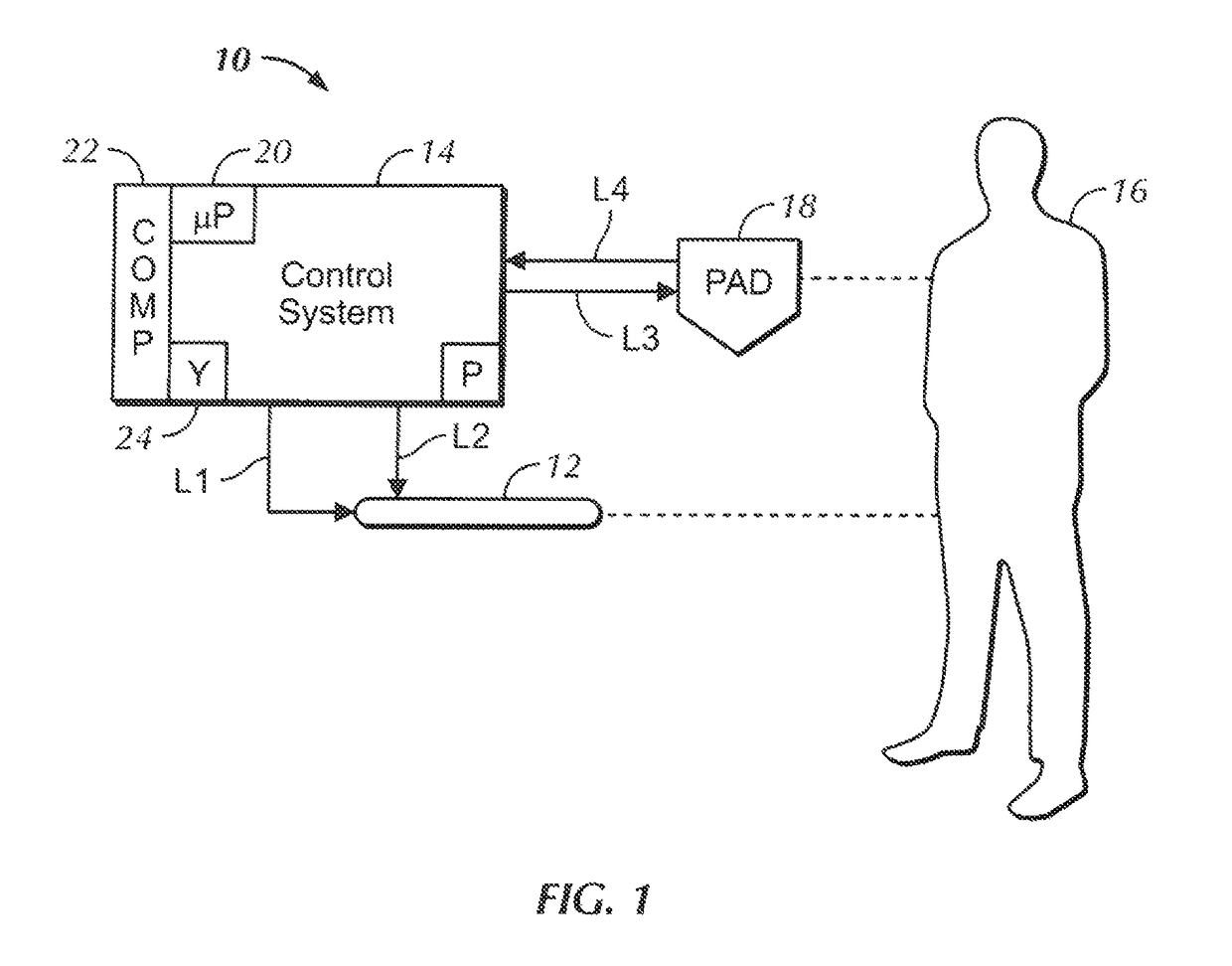
[0020]Referring initially to FIG. 1, in accordance with present principles, a system 10 may include an intravascular heat exchange catheter 12 controlled by a control system 14 to control patient temperature, e.g., to prevent the patient 16 from becoming febrile or to induce therapeutic hypothermia in the patient 16. In the catheter, working fluid (also referred to as “coolant”) such as but not limited to saline circulates (typically under the influence of a pump “P” in the control system) in a closed loop from the control system 14, through a fluid supply line L1, through the catheter 12, and back to the system 14 through a fluid return line L2, such that no coolant enters the body. While certain preferred catheters are disclosed herein, it is to be understood that other catheters can be used in accordance with present principles, including, without limitation, any of the catheters disclosed above or in the following U.S. patents, all incorporated herein by reference: U.S. Pat. Nos...


PUM


Abstract

A peristaltic pump has an arcuate raceway with a partially concave inner surface extending through an arc of at least one hundred eighty degrees (180°). The arc defines a midpoint, and a rotor faces the inner surface of the raceway and is both rotatable relative to the raceway and translationally movable relative to the raceway between a pump position, wherein the rotor is spaced from the midpoint a first distance, and a tube load position, wherein the rotor is spaced from the midpoint a second distance greater than the first distance. A motor is coupled to the rotor to rotate the rotor plural are rollers arranged on the rotor to contact tubing disposed between the rotor and the raceway when the rotor is in the pump position. The motor is prevented from stopping at a predetermined angular position to facilitate loading and unloading tubing.

Description

FIELD OF THE INVENTION[0001]The present application relates generally to heat exchange systems for patient temperature control with easy loading high performance peristaltic pumps.BACKGROUND OF THE INVENTION[0002]Patient temperature control systems have been introduced to prevent fever in patients in the neuro ICU due to suffering from sub-arachnoid hemorrhage or other neurologic malady such as stroke. Also, such systems have been used to induce mild or moderate hypothermia to improve the outcomes of patients suffering from such maladies as stroke, cardiac arrest, myocardial infarction, traumatic brain injury, and high intracranial pressure. Examples of intravascular heat exchange catheters are disclosed in U.S. Pat. Nos. 7,914,564, 6,416,533, 6,409,747, 6,405,080, 6,393,320, 6,368,304, 6,338,727, 6,299,599, 6,290,717, 6,287,326, 6,165,207, 6,149,670, 6,146,411, 6,126,684, 6,306,161, 6,264,679, 6,231,594, 6,149,676, 6,149,673, 6,110,168, 5,989,238, 5,879,329, 5,837,003, 6,383,210, 6...

Claims


Application Information

Patent Timeline
Patent Type & Authority Patents(United States)
IPC IPC(8): F04B43/12A61M5/142A61F7/00
CPCF04B43/1223F04B43/1276F04B43/1284A61M5/14232A61F2007/0054F04B43/1253F04B43/12F04B43/1292
Inventor HENDRICKS, AUSTIN REIDPAMICHEV, CHRISTO PETROVGURUKULA, VENKATA VISHNUDABROWIAK, JEREMY THOMAS
Owner ZOLL CIRCULATION
Why Eureka
Try Eureka