Slot array antenna

a technology of array antennas and antenna elements, applied in the direction of individual energised antenna arrays, waveguide mouths, waveguides, etc., can solve the problems of affecting the efficiency of the antenna, and difficult to dispose of antenna elements with a high density

Active Publication Date: 2017-10-10
NIDEC CORP +1
View PDF58 Cites 39 Cited by
  • Summary
  • Abstract
  • Description
  • Claims
  • Application Information

AI Technical Summary

Benefits of technology

[0032]In accordance with an embodiment of the present disclosure, the phase of an electromagnetic wave propagating in a waveguide can be adjusted, whereby a desired excitation state can be realized at the position of each antenna element. This allows a plurality of antenna elements to perform a proper radiation that is adapted to the purpose.

Problems solved by technology

However, in the case where the frequency of an electromagnetic wave to be transmitted or received by an array antenna is a high frequency, e.g., above 30 gigahertz (GHz), a microstrip line will incur a large dielectric loss, thus detracting from the efficiency of the antenna.
However, by using a hollow waveguide, it is difficult to dispose antenna elements with a high density, because the hollow portion of a hollow waveguide needs to have a width which is equal to or greater than a half wavelength of the electromagnetic wave to be propagated, and the body (metal wall) of the hollow waveguide itself also needs to be thick enough.
However, this slot array antenna was not able to allow a plurality of antenna elements to perform a proper radiation that is adapted to the purpose.

Method used


Image

  • Slot array antenna
  • Slot array antenna
  • Slot array antenna

Examples


embodiment 1

[0203]Embodiment 1 relates to a slot array antenna (which hereinafter may simply be referred to as an “array antenna”) to which standing-wave series feed is applied in order to excite a plurality of slots with an equiamplitude and equiphase and achieve a high gain. The slot array antenna according to the present disclosure is not limited to a construction where the plurality of slots are excited with an equiamplitude and equiphase; however, for ease of understanding the invention, the present embodiment will illustrate a slot array antenna which achieves equiamplitude-equiphase excitation to maximize the gain, this being the simplest example.

[0204]First, the principle of standing-wave series feed will be described.

[0205]FIG. 10 is a principle diagram showing an exemplary array antenna under ideal standing-wave series feed. FIG. 11 is a Smith chart representation of an impedance locus at different points in the array antenna shown in FIG. 10, as viewed from the antenna input terminal...

embodiment 2

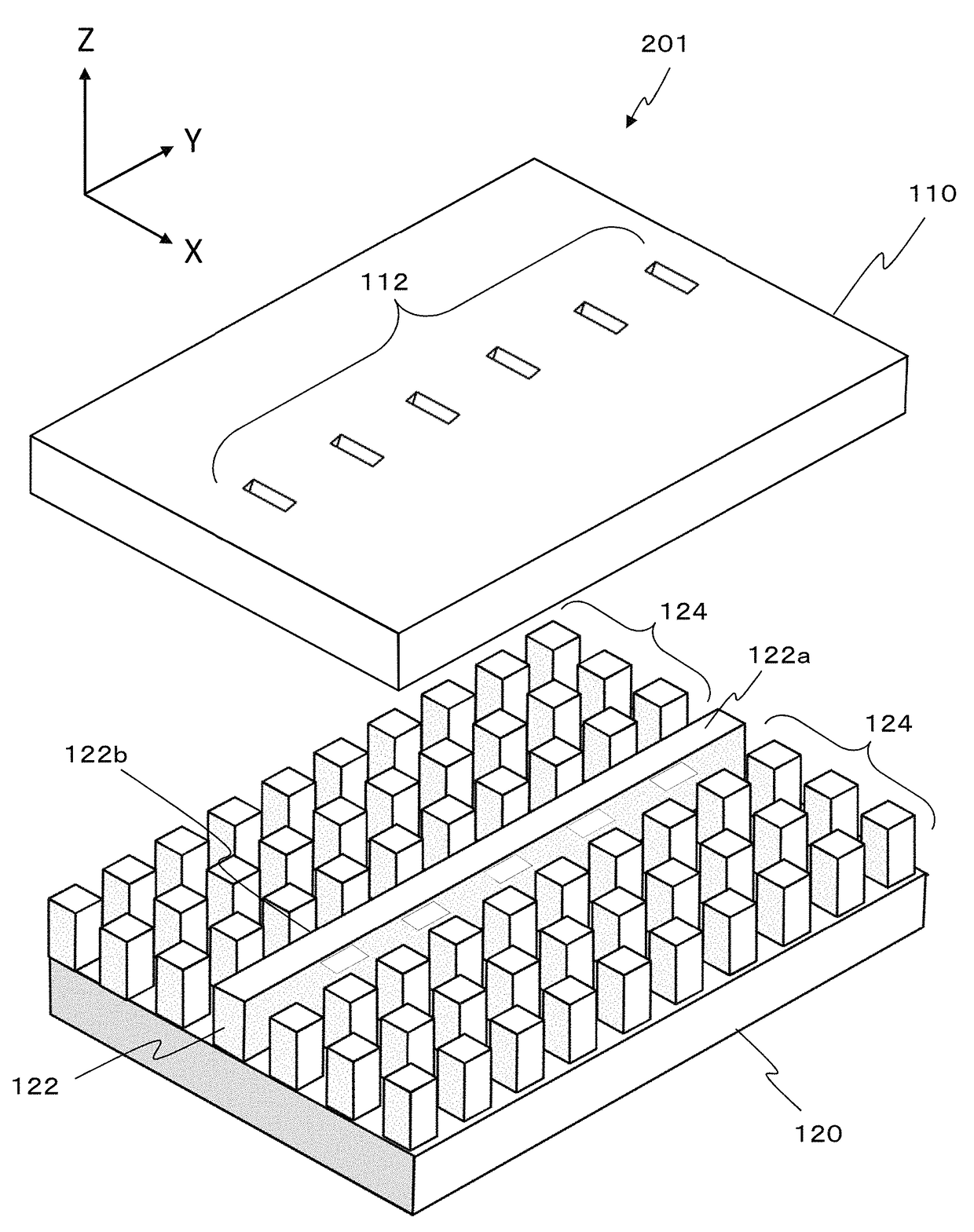
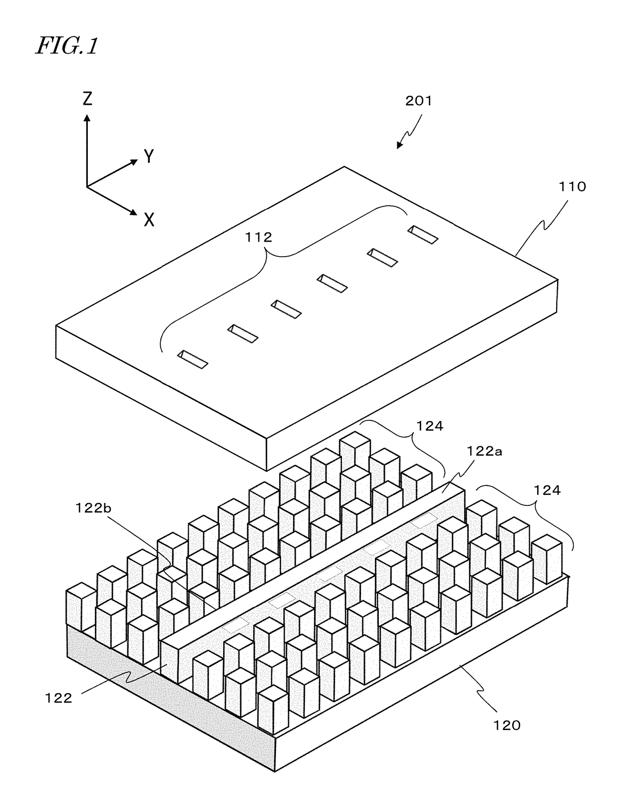
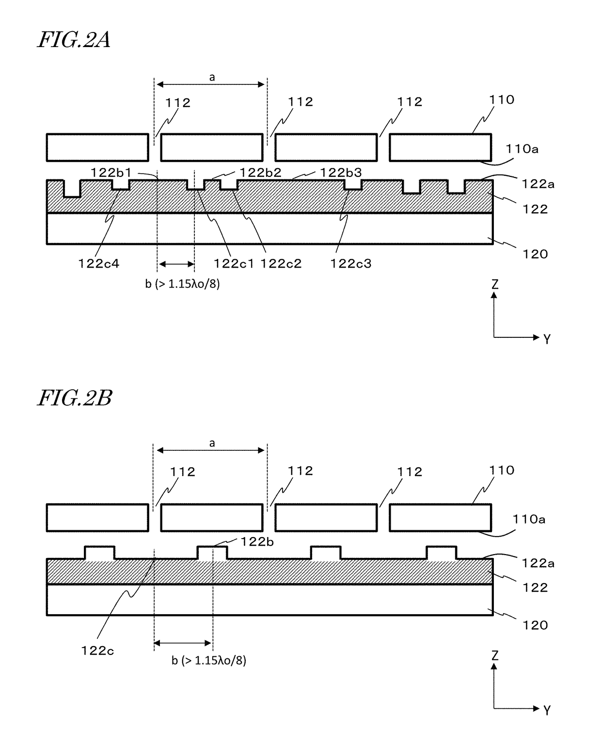
[0231]FIG. 19A is a perspective view showing the structure of an array antenna 1001 according to a second embodiment of the present disclosure. FIG. 19B is a cross-sectional view of the array antenna shown in FIG. 19A, taken along a plane which extends through the centers of a plurality of radiating slots 112 and the center of a ridge 122. In the present embodiment, too, according to the principle of standing-wave series feed, every radiating slot 112 is designed in a resonant state so that its radiation impedance equals its pure resistance component. Moreover, all radiating slots 112 are of an identical shape.

[0232]In the present embodiment, in order to control the wavelength and phase of a standing wave, structures that are distinct from other partial paths, i.e., bumps 122b, are provided as additional elements on the WRG. The bumps 122b are disposed so that, in each region between two adjacent radiating slots 112, a combination of identical bumps 122b are provided symmetrically o...

application example 1

[0287]Next, as an Application Example of utilizing the above-described slot array antenna, an instance of an onboard radar system including a slot array antenna will be described. A transmission wave used in an onboard radar system may have a frequency of e.g. 76 gigahertz (GHz) band, which will have a wavelength λo of about 4 mm in free space.

[0288]In safety technology of automobiles, e.g., collision avoidance systems or automated driving, it is particularly essential to identify one or more vehicles (targets) that are traveling ahead of the driver's vehicle. As a method of identifying vehicles, techniques of estimating the directions of arriving waves by using a radar system have been under development.

[0289]FIG. 33 shows a driver's vehicle 500, and a preceding vehicle 502 that is traveling in the same lane as the driver's vehicle 500. The driver's vehicle 500 includes an onboard radar system which incorporates a slot array antenna according to any of the above-described embodimen...


PUM


Abstract

A slot array antenna includes: an electrically conductive member having an electrically conductive surface and slots therein, the slots being arrayed in a first direction which extends along the conductive surface; a waveguide member having an electrically conductive waveguide face which opposes the slots and extends along the first direction; and an artificial magnetic conductor extending on both sides of the waveguide member. At least one of the conductive member and the waveguide member includes dents on the conductive surface and / or the waveguide face, the dents each serving to broaden a spacing between the conductive surface and the waveguide face relative to any adjacent site. The dents include a first, second, and third dents which are adjacent to one another and consecutively follow along the first direction. A distance between centers of the first and second dents is different from a distance between centers of the second and third dents.

Description

[0001]This is a continuation of International Application No. PCT / JP2016 / 083622, with an international filing date of Nov. 4, 2016, which claims priority of Japanese Patent Application No. 2015-217657 filed Nov. 5, 2015, and Japanese Patent Application No. 2016-174841 filed Sep. 7, 2016, the entire contents of which are hereby incorporated by reference.BACKGROUND[0002]1. Technical Field[0003]The present disclosure relates to a slot array antenna.[0004]2. Description of the Related Art[0005]An array antenna including a plurality of antenna elements (hereinafter also referred to “radiating elements”) that are arrayed on a line or a plane finds its use in various applications, e.g., radar and communication systems. In order to radiate electromagnetic waves from an array antenna, it is necessary to supply electromagnetic waves (e.g., radio-frequency signal waves) to each antenna element, from a circuit which generates electromagnetic waves (“feed”). Such feed is performed via a waveguid...

Claims


Application Information

Patent Timeline
Patent Type & Authority Patents(United States)
IPC IPC(8): H01Q13/10H01Q1/32H01Q21/06H01Q13/06
CPCH01Q21/064H01Q13/10H01Q13/06H01Q1/3266H01P3/123H01Q21/00H01Q1/3233H01Q13/20
Inventor KIRINO, HIDEKIKAMO, HIROYUKI
Owner NIDEC CORP
Why Eureka
Try Eureka