High-isolation slot antenna array

A technology of slot antenna and antenna array, which is applied in the direction of slot antenna, antenna coupling, antenna unit combination with different polarization directions, etc., can solve the problems of deterioration of radiation characteristics, low isolation of antenna array, and decrease of isolation, etc., to achieve The effect of reducing adverse effects, small occlusion effects, and high isolation

Active Publication Date: 2014-10-29
ZHONGTIAN BROADBAND TECH +1
View PDF4 Cites 79 Cited by
  • Summary
  • Abstract
  • Description
  • Claims
  • Application Information

AI Technical Summary

Problems solved by technology

Common slot antennas can be used to form antenna arrays for multi-polarization MIMO, but the isolation of these antenna arrays is not very high
[0003] Since the metal ground plane of the slot antenna can induce currents in multiple directions, the radiation of these currents will cause a decrease in the isolation between the antennas. When antennas with different polarization directions are co-located at one place, due to the The closer the distance, the stronger the mutual induction current, making the problem of antenna isolation more serious; in addition, when antennas with different radiation polarization directions are co-located, the shielding of the metal ground plane of one antenna to the radiation field of the other antenna will The directivity of another antenna is affected, especially the radiation characteristics of the blocked direction will be deteriorated

Method used


Image

  • High-isolation slot antenna array
  • High-isolation slot antenna array

Examples


Embodiment Construction

[0013] The present invention will be further described below in conjunction with drawings and embodiments.

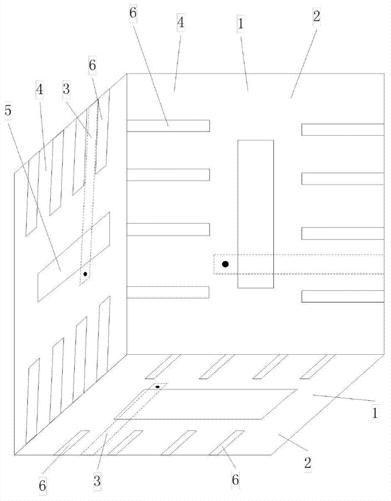
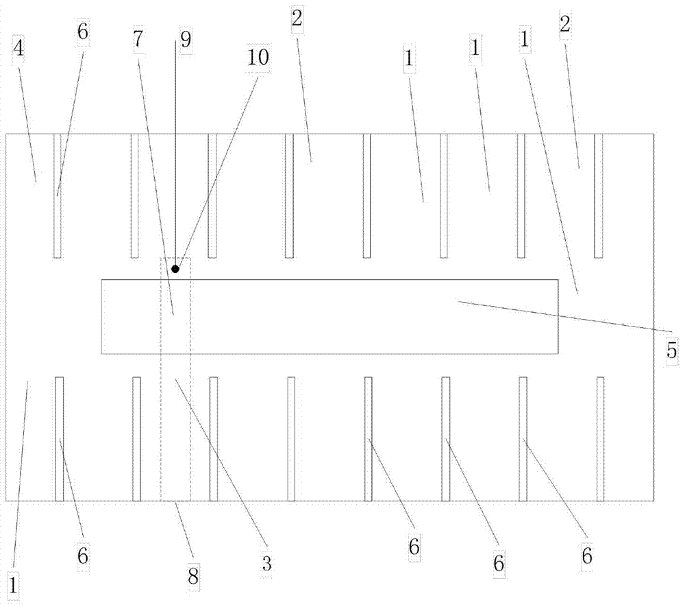
[0014] The technical scheme adopted in the present invention is: the high-isolation slot antenna array is composed of three slot antennas 1 placed together and whose radiation polarization directions are orthogonal to each other; The microstrip feeder 3 and the metal ground plane 4 are composed of a radiation slot 5 and a plurality of isolation slots 6 on the metal ground plane 4; the radiation slot 5 is rectangular in shape; the isolation slot 6 is located around the radiation slot 5, and its The shape is a narrow rectangle; the isolation slits 6 are all parallel to each other, and the long side direction of the radiation slot 5 is perpendicular to the long side direction of the isolation slit 6; the isolation slits 6 are all parallel to each other, and one end of the isolation slit 6 is either short-circuited or extended to The edge of the metal ground plane 4 makes t...


PUM


Abstract

A high-isolation slot antenna array relates to a multi-input multi-output antenna. The antenna is composed of three slot antennas which are arranged together, the radiation polarization directions of every two slot antennas intersect, and each slot antenna is formed by a micro-strip feeder on a dielectric substrate and a metal ground plane. A radiation slit and a plurality of isolation slots are formed in the metal ground plane. The isolation slots are formed in the periphery of the radiation slit, and the isolation slots are parallel to each other. The long side direction of the radiation slit is perpendicular to the long side direction of the isolation slots, and the length of the isolation slots enables the resonance frequency to be lower than the working efficiency of the antennas. An antenna input output port is formed in one end of the micro-strip feeder, a metal short circuit needle is arranged at the tail end of a micro-strip feeder conduction band at the other end of the micro-strip feeder, and the conduction band and the metal ground plane are connected on the edge of the radiation slit through the metal short circuit needle. The antenna can effectively reduce adverse effects of shielding and isolation of the metal ground plane on antenna normal radiation.

Description

technical field [0001] The invention relates to a microwave antenna, in particular to a high-isolation slot antenna array. Background technique [0002] Multiple-input multiple-output (MIMO) technology is an effective technology for improving information transmission capacity. Multi-polarization MIMO is a commonly used technology. The antenna array of a multi-polarization MIMO system has two or more unit antennas to form an antenna These element antennas have mutually orthogonal radiation polarization directions. In order to ensure better channel isolation, it is required that these element antennas with different polarization directions have better isolation. Common slot antennas can be used to form antenna arrays for multi-polarization MIMO, but the isolation of these antenna arrays is not very high. [0003] Since the metal ground plane of the slot antenna can induce currents in multiple directions, the radiation of these currents will cause a decrease in the isolation b...

Claims


Application Information

Patent Timeline
Patent Type & Authority Applications(China)
IPC IPC(8): H01Q1/52H01Q13/10H01Q21/24
Inventor 刘蕾蕾刘超薄亚明吴振华
Owner ZHONGTIAN BROADBAND TECH
Why Eureka
Try Eureka