
Heating device for evaporation of OLED material

a heating device and oled material technology, applied in the direction of electric/magnetic/electromagnetic heating, sublimation, separation processes, etc., can solve the problems of increasing work load, reducing manufacturing efficiency, and potential risk of quality change of oled material, so as to reduce the temperature of oled material

Active Publication Date: 2017-10-17
TCL CHINA STAR OPTOELECTRONICS TECH CO LTD
View PDF21 Cites 4 Cited by
  • Summary
  • Abstract
  • Description
  • Claims
  • Application Information

AI Technical Summary

Benefits of technology

[0008]An object of the present invention is to provide a heating device for evaporation of an OLED material, which keeps a gas release hole at a relatively high temperature while lowers down the temperature of an OLED material to prevent gaseous molecules of the OLED material from getting solidified at the gas release hole thereby avoiding jamming of the gas release hole, maintaining manufacturing efficiency, and eliminating the potential risk of quality change of the OLED material resulting from contacting moisture and oxygen.
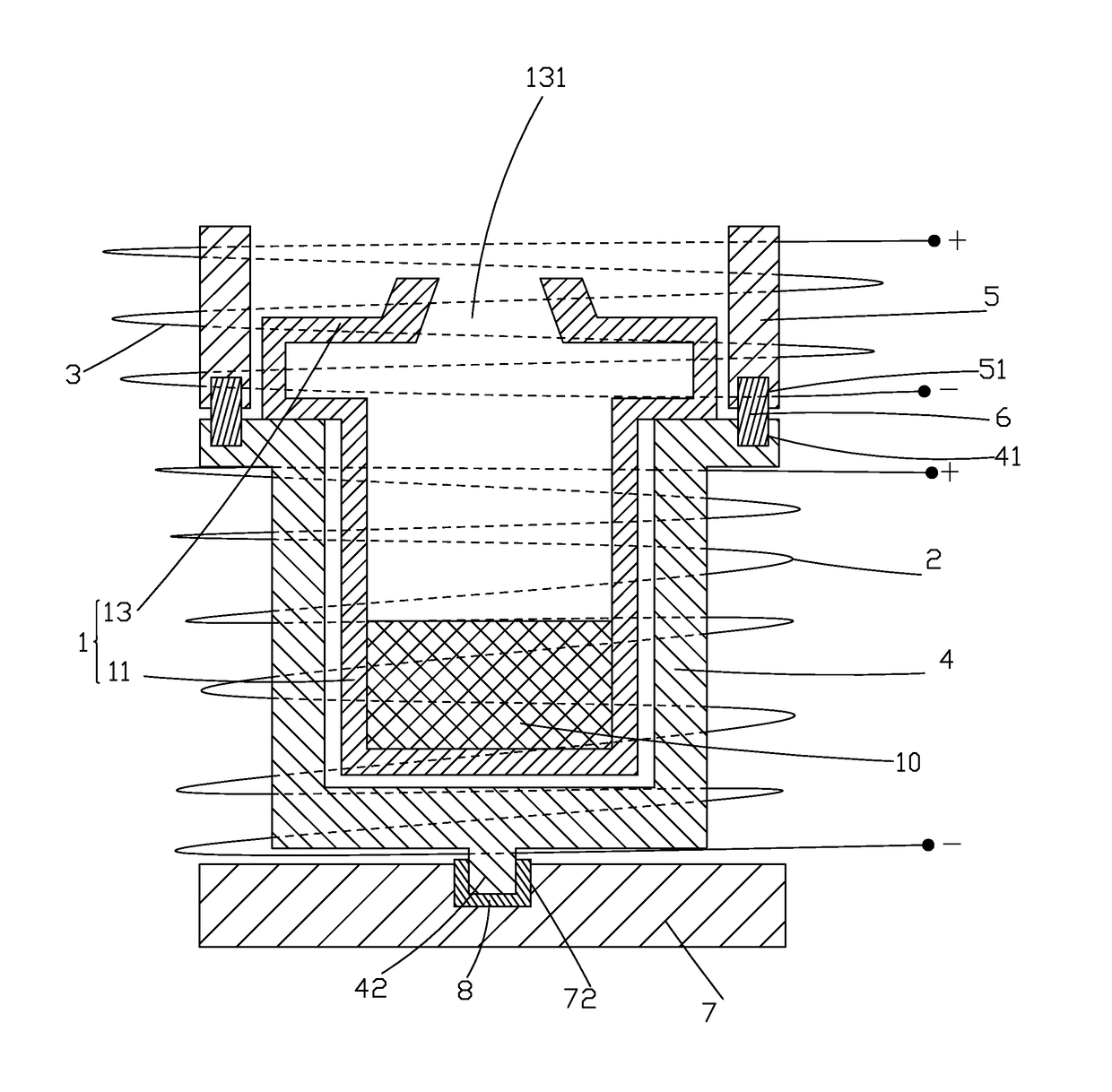
[0019]The efficacy of the present invention is that the present invention provides a heating device for evaporation of an OLED material, which comprises two sets of upper and lower heating coils and two sets of upper and lower thermally conductive temperature homogenizing sleeves to respectively control the heating temperatures of the top cover section and the body section of the crucible in order to achieve lowering the temperature of the OLED material and at the same time, maintaining the gas release hole of the crucible at a relatively high temperature so as to prevent the gaseous molecules of the OLED material from getting solidified at the gas release hole thereby avoiding blocking of the gas release hole, maintaining manufacturing efficiency, and eliminating the potential risk of quality change resulting from the OLED material contacting moisture and oxygen.

Problems solved by technology

This lowers the manufacturing efficiency, increases work load, and also bring potential risk of quality change of the OLED material due to the OLED material being exposed to the atmosphere and thus contacting moisture and oxygen.

Method used


Image

  • Heating device for evaporation of OLED material
  • Heating device for evaporation of OLED material
  • Heating device for evaporation of OLED material

Examples


Embodiment Construction

[0027]Referring to FIG. 4, a schematic view is given to show a heating device for evaporation of an OLED (Organic Light-Emitting Diode) material according to an embodiment of the present invention. The heating device for evaporation of an OLED material comprises a crucible 1 for receiving and containing therein an OLED material 10. The crucible 1 comprises a body section 11 and a top cover section 13 connected to the body section 11. The top cover section 13 has a top having a center in which a gas release hole 131 is formed. The OLED material 10 can be an organic material used to form a film of an OLED organic layer or a metallic material, such as LIF, Mg / Ag, Li / Al, used to form a film of an OLED metal cathode. The gas release hole 131 provides a channel for the gaseous molecules of the OLED material, after being heated and evaporated, to flow out.

[0028]A key point here is that the heating device for evaporation of an OLED material further comprises a lower heating coil 2 that surr...


PUM

PropertyMeasurementUnit
diameteraaaaaaaaaa
heightaaaaaaaaaa
temperatureaaaaaaaaaa

Abstract

The present invention provides a heating device for evaporation of an OLED material, which includes a crucible (1) for receiving and containing therein an OLED material (10), a lower heating coil (2) surrounding outside an outer circumference of the body section (11) of the crucible (1), an upper heating coil (3) surrounding outside an outer circumference of the top cover section (13) of the crucible (1), a lower thermally conductive temperature homogenizing sleeve (4) arranged between the body section (11) and the lower heating coil (2), an upper thermally conductive temperature homogenizing sleeve (5) arranged between the top cover section (13) and the upper heating coil (3), and a thermal insulation ring (6) arranged between the upper and lower thermally conductive temperature homogenizing sleeves (5, 4). The upper and lower heating coils (3, 2) are each connected to a power supply for individually controlling a heating temperature of each of the top cover section (13) and the body section (11). The heating device prevents gaseous molecules of the OLED material (10) from getting condensed and solidified at a gas release hole (131) of the crucible (1) so as to prevent jamming and blocking of the gas release hole (131).

Description

BACKGROUND OF THE INVENTION[0001]1. Field of the Invention[0002]The present invention relates to the field of OLED (Organic Light-Emitting Diode) manufacture, and in particular to a heating device for vapor deposition of an OLED material.[0003]2. The Related Arts[0004]An OLED (Organic Light-Emitting Diode) is a flat panel displaying technique of extremely prosperous future and it shows excellent displaying performance and also possesses various advantages, such as being self-luminous, simple structure, being ultra-thin, fast response speed, wide view angle, low power consumption, and being capable of achieving flexible displaying and is thus regarded as a “dream display”. In addition, the investment of the manufacturing installation is far less than that of liquid crystal displays so that it has attracted the attention of major display manufacturers and becomes the mainstream of the three-generation display devices of the field of display technology.[0005]An OLED often comprises: a ...

Claims


Application Information

Patent Timeline
Patent Type & Authority Patents(United States)
IPC IPC(8): B01D7/00H05B6/06H01L51/56C23C14/26C23C14/24H05B6/36H05B6/26B05D1/00C23C14/14H01L51/00
CPCC23C14/243C23C14/26H01L51/56H05B6/06H05B6/26H05B6/36H05B6/367B05D1/60C23C14/14H01L51/001H10K71/00H10K71/164
Inventor LIU, YAWEI
Owner TCL CHINA STAR OPTOELECTRONICS TECH CO LTD
Learn More