
Multi-feed antenna optimized for non-50 Ohm operation

a multi-feed antenna and 50 ohm technology, applied in the field of wireless communication, can solve the problems of increasing cost and size requirements, reducing the efficiency of power transfer through the device, and amplifiers tend to have natural device impedances, so as to eliminate the impedance transforming circuit

Active Publication Date: 2017-11-14
KYOCERA AVX COMPONENTS (SAN DIEGO) INC
View PDF6 Cites 4 Cited by
  • Summary
  • Abstract
  • Description
  • Claims
  • Application Information

AI Technical Summary

Benefits of technology

The patent describes an antenna that can match its impedance to the surrounding environment, resulting in better signal quality. This is achieved through the use of obstacle transformers that change the electrical properties of the antenna to match the characteristics of the surrounding system or circuit. The antenna can also operate at different frequencies by simply connecting the RF circuitry to the antenna. No additional circuits are needed. This design improves the performance and reliability of antennas in various applications.

Problems solved by technology

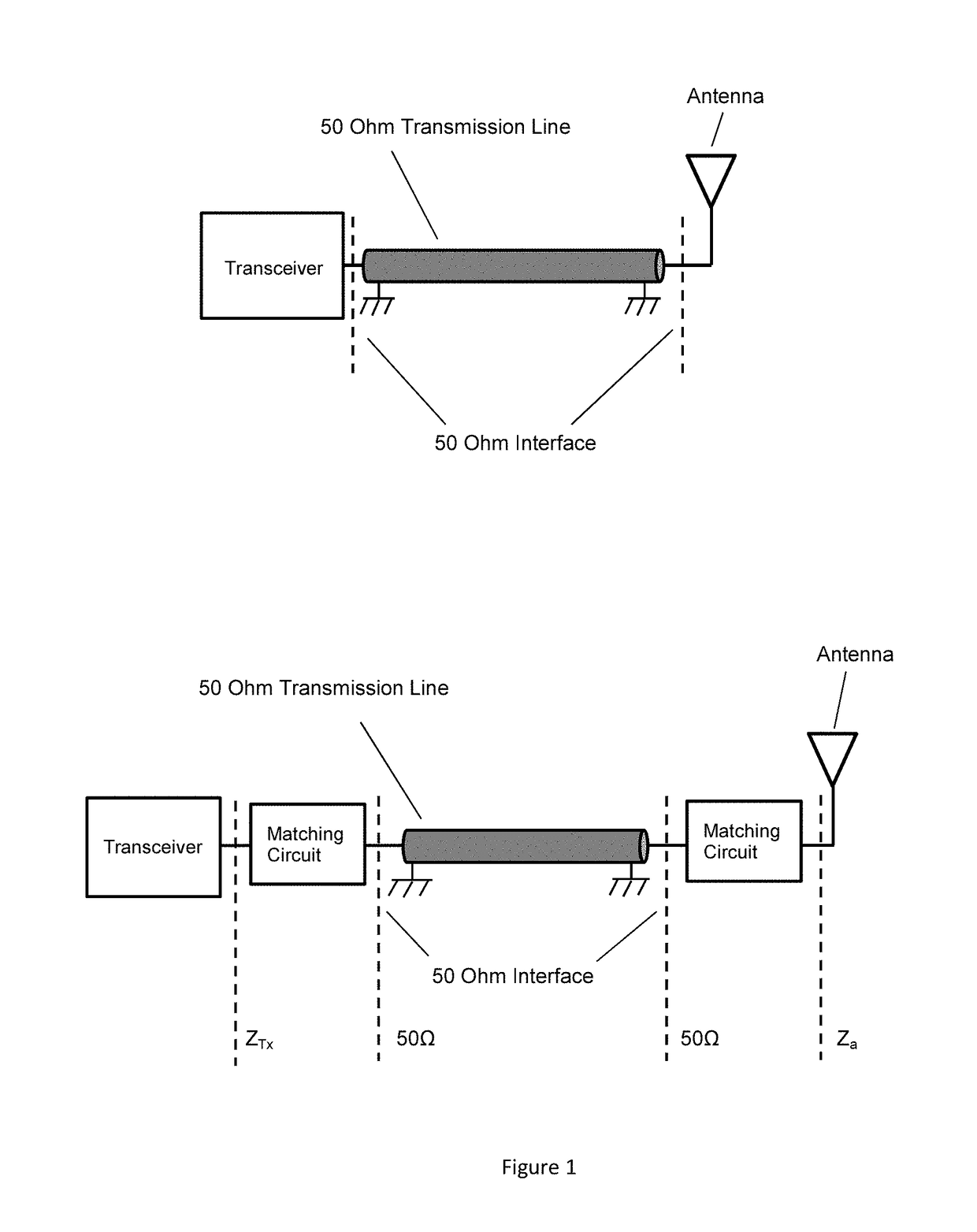
The drawback with this approach is that some components such as antennas and power amplifiers tend to have natural device impedances that are substantially different than 50 Ohms.
The matching circuit will have losses associated with it as well as cost, resulting in reduced efficiency in terms of power transfer through the device along with increased cost and size requirements.
The losses incurred in the matching circuit of an antenna will result in reduced efficiency of the radiated signal.
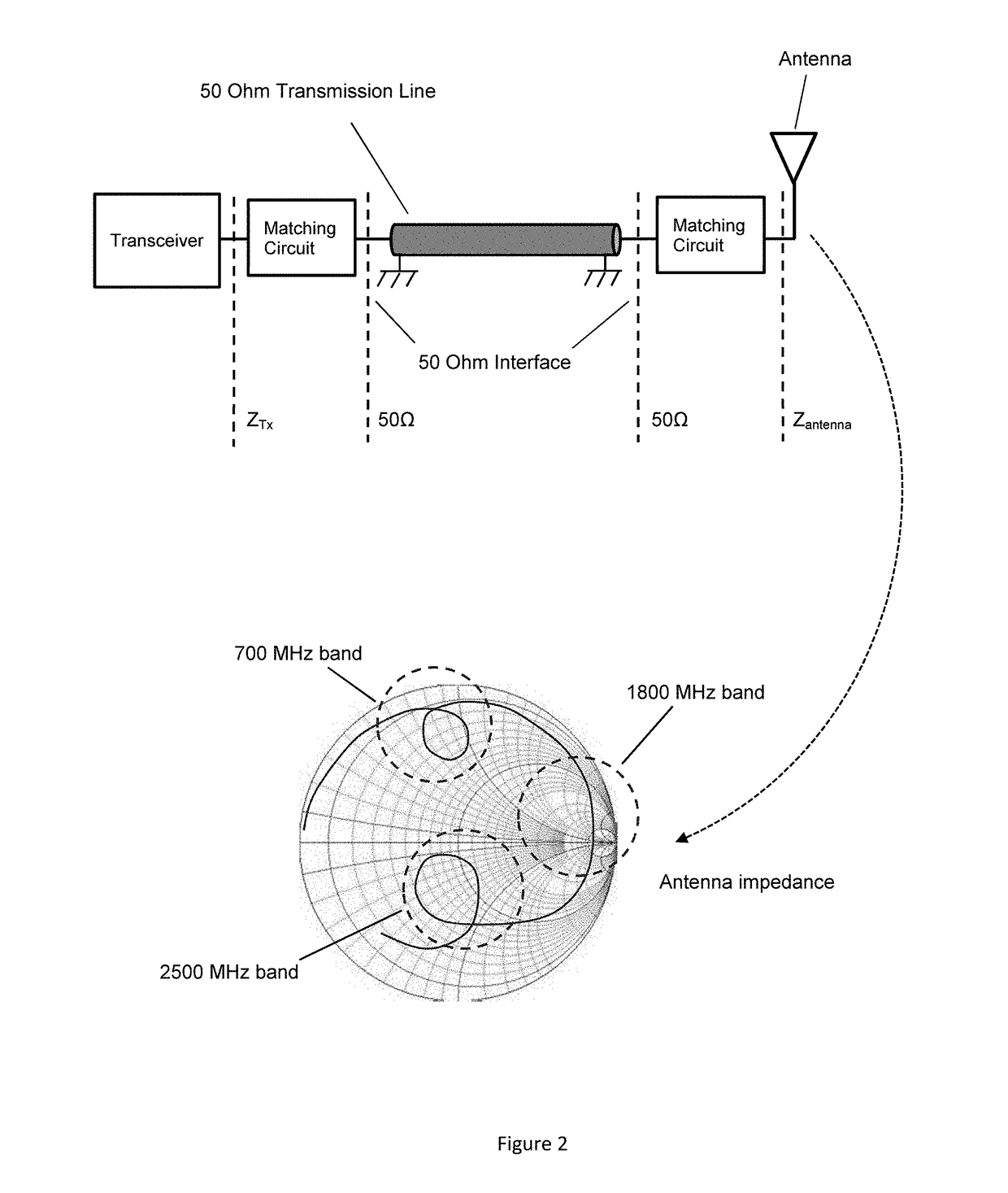
Designing a matching circuit to transform impedances of the antenna at low frequencies as well as high frequencies results in an increase in matching circuit losses and a reduction in available bandwidth.

Method used


Image

  • Multi-feed antenna optimized for non-50 Ohm operation
  • Multi-feed antenna optimized for non-50 Ohm operation
  • Multi-feed antenna optimized for non-50 Ohm operation

Examples


Embodiment Construction

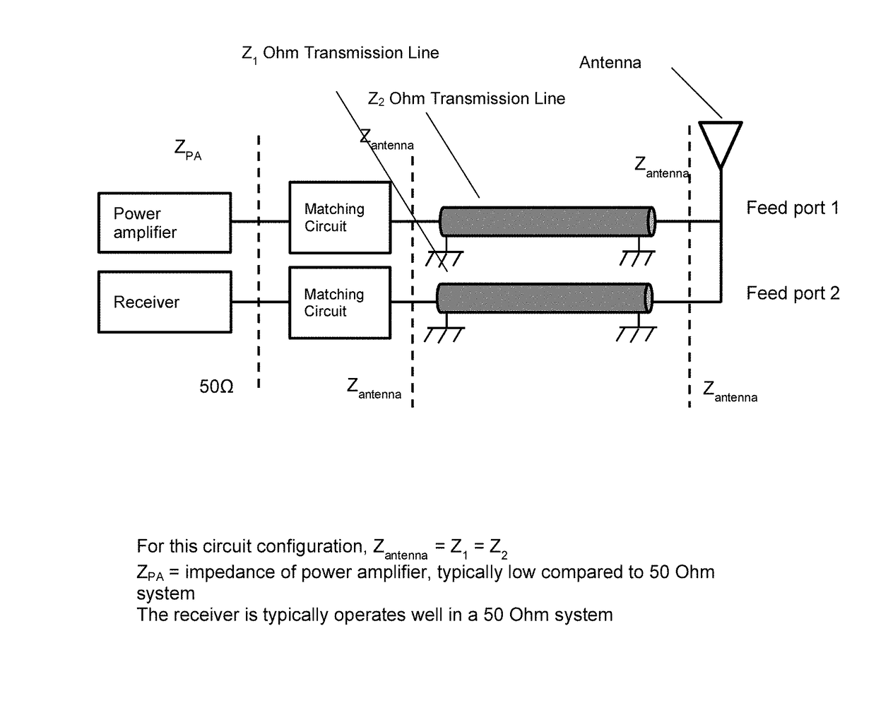
[0021]This patent describes a method of designing multi-port antennas and connecting these antenna ports to transceivers or other components in an RF system, where the antenna ports are matched to the natural impedance of the antenna at the frequency range that the antenna port is optimized to. Benefits in terms of reduced cost, reduced circuit losses, and a reduction in area required to integrate matching circuits can be had by reducing or eliminating the need to transform impedances as antennas, transmission lines, and circuit components are configured into transceiver systems.

[0022]One embodiment of this invention is an antenna containing three feed ports, with port 1 configured for use at low frequency bands, port 2 configured for use at mid-frequency bands, and port 3 configured for use at high frequency bands. The antenna impedance at the three feed ports is the natural frequency of the antenna. A transmission line is attached to each feed port, with the characteristic impedan...


PUM


Abstract

A multi-feed antenna is described where the antenna is optimized for the natural impedance state per frequency band. Multiple feed points are accessed as a function of frequency and use case to provide a feed port that is operating at the natural impedance state for the antenna structure. Impedance transforming circuits can be applied to the feed point to form impedance matching circuits to transform the antenna impedance to a characteristic impedance of the system or circuit interfacing with the antenna. The impedance transforming circuits can be eliminated and the RF circuitry interfacing with the antenna can be configured to operate at the natural frequency of the antenna.

Description

CROSS-REFERENCE TO RELATED APPLICATIONS[0001]This application claims benefit of priority with U.S. Provisional Ser. No. 61 / 955,059, filed Mar. 18, 2014, titled “”; the contents of which are hereby incorporated by reference.FIELD OF INVENTION[0002]The present invention relates generally to the field of wireless communication. In particular, the present invention relates to antennas for multi-frequency band operation and the optimization of these antennas for improved impedance matched states and optimal power transfer.BACKGROUND OF THE INVENTION[0003]Prior to standardization to the 50 Ohm characteristic impedance for RF and microwave components and test equipment, characteristic impedances of components and systems were chosen based on the application. For instance, for high power applications 30 to 40 Ohms was chosen for coaxial transmission lines to accommodate maximum power handling. If an application required minimal losses from the transmission lines, then a 93 Ohm transmission ...

Claims


Application Information

Patent Timeline
IPC IPC(8): H01Q1/44H01Q1/50H03H7/38H01Q9/04H01Q5/328H01Q5/40H01Q5/35
CPCH01Q1/50H03H7/38H01Q9/0421H01Q5/328H01Q5/40H01Q5/35H01Q9/40H01Q9/42H01Q21/28H01Q21/30H01Q5/335
Inventor DESCLOS, LAURENTSHAMBLIN, JEFFREY
Owner KYOCERA AVX COMPONENTS (SAN DIEGO) INC
Learn More