
Burner

a burner and burner technology, applied in the field of burners, can solve problems such as unstable ignition, and achieve the effects of improving safety, stabilizing ignition, and promoting ignition

Active Publication Date: 2017-11-21
IHI CORP
View PDF18 Cites 15 Cited by
  • Summary
  • Abstract
  • Description
  • Claims
  • Application Information

AI Technical Summary

Benefits of technology

The design stabilizes and promotes ignition even at low oxygen concentrations, improves safety by preventing premature ignition, and facilitates efficient carbon dioxide capture post-combustion by maintaining a high carbon dioxide ratio in the flue gas.

Problems solved by technology

However, in a case where only the recirculated flue gas is used as the carrying medium without mixing the oxygen into the recirculated flue gas, since the oxygen concentration in the recirculated flue gas is as low as approximately 3% to 5%, the oxygen is not sufficiently supplied to a pulverized coal mixed flow even if the combustion air is supplied from the periphery at the time of the combustion, and thus, a problem may arise that the ignition becomes unstable.

Method used


Image

  • Burner
  • Burner
  • Burner

Examples


first embodiment

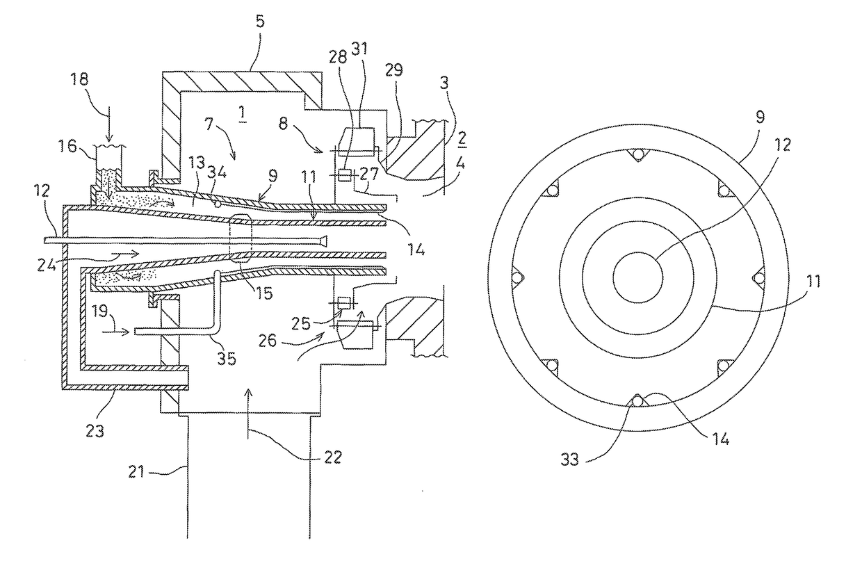
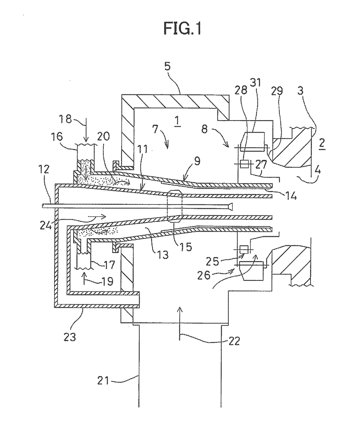
[0020]First, in FIG. 1, a description will be given on a burner 1 according to the present invention.

[0021]In FIG. 1, reference numeral 2 denotes a furnace and reference numeral 3 denotes a furnace wall of the furnace 2. A throat 4 is provided on the furnace wall 3, a wind box 5 is provided on the furnace wall 3 on an opposite side of a furnace 2, and the burner 1 is provided inside the wind box 5 concentrically with the throat 4.

[0022]The burner 1 comprises a nozzle main body 7 and a secondary air regulator 8 provided so as to surround a tip portion an end portion of the furnace inner side) of the nozzle main body 7.

[0023]The nozzle main body 7 comprises an outer nozzle 9 and an inner nozzle 11 which are concentrically provided, and an oil burner 12 arranged on a center line of the inner nozzle 11, and each of the outer nozzle 9 and the inner nozzle 11 has a diameter reducing structure where a diameter gradually decreases respectively. Further, each of the shape of the cross sectio...

second embodiment

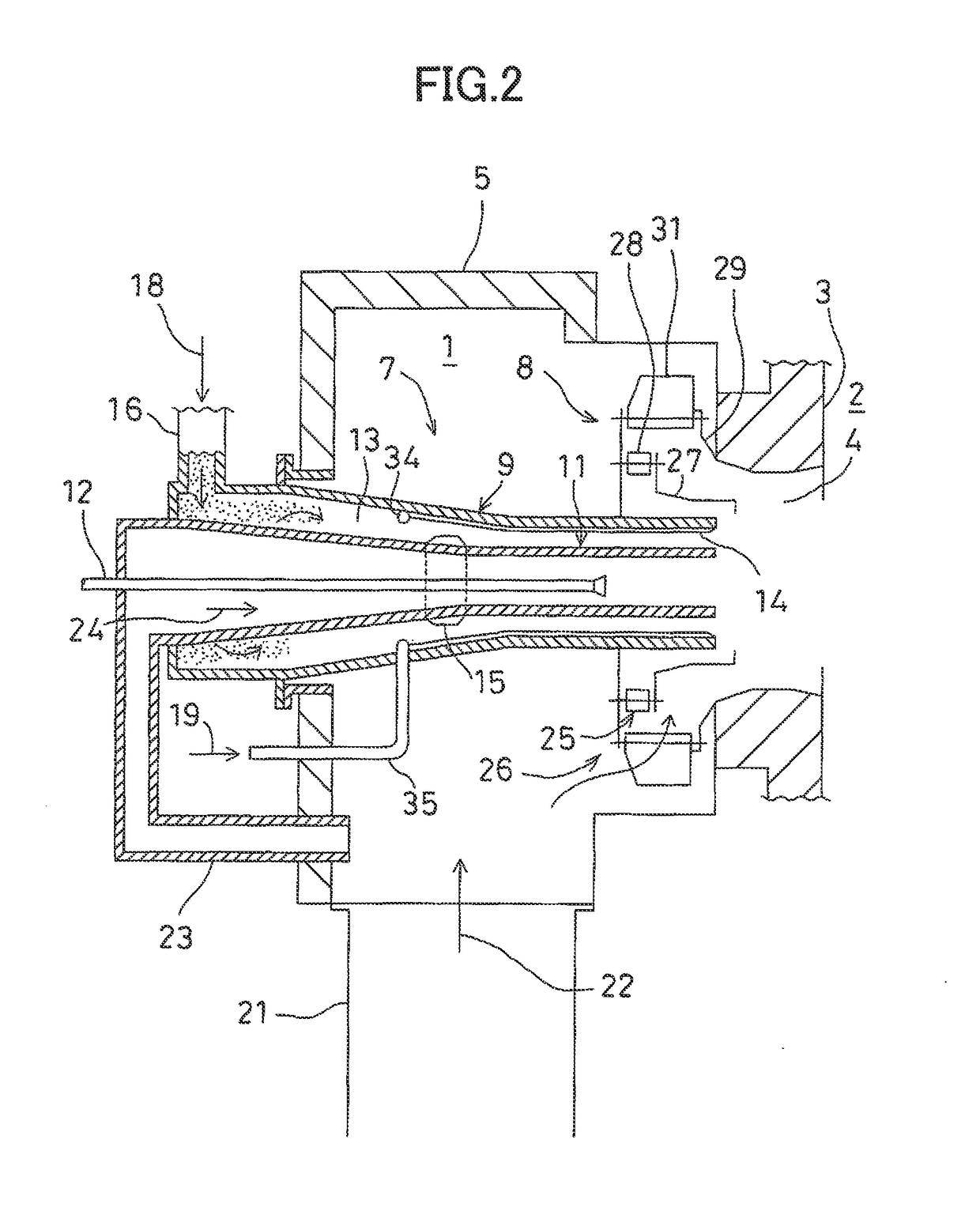
[0049]Next, referring to FIG. 2 and FIG. 3, description will be given on a second embodiment according to the present invention. It is to be noted that, in FIG. 2 and FIG. 3, the same component as shown in FIG. 1 is referred by the same symbol, and detailed description is omitted.

[0050]In a burner 1 according to the second embodiment, an oxygen-containing gas intake pipe 33 which forms a flow path of an oxygen-containing gas 19 is inserted inside each deflector angle 14, a ring pipe 34 which is put over each deflector angle 14 is connected to a base end of the deflector angle 14, and each oxygen-containing gas intake pipe 33 and the ring pipe 34 communicate with each other.

[0051]Further, an oxygen-containing gas supply pipe 35 penetrating an outer nozzle 9 is connected to the ring pipe 34, she oxygen-containing gas supply pipe 35 is connected to an oxygen-containing gas supply source (not shown), and the oxygen-containing gas 19 such as pure oxygen or a mixed gas of oxygen and carbo...

third embodiment

[0059]Next, referring to FIG. 4, description will be given on a third embodiment according to the present invention. It is to be noted that, in FIG. 4, the same component as shown in FIG. 1 is referred by the same symbol, and detailed, description is omitted.

[0060]In the third embodiment, a concentration adjustment ring 15 has a hollow structure, and a plurality of oxygen-containing gas spurt out holes 37 are formed at a tip surface of the concentration adjustment ring 15 at an equal angle pitch.

[0061]Further, the concentration adjustment ring 15 is inserted in an inner nozzle 11 and connected with an oxygen-containing gas supply pipe 38 penetrating a peripheral wall of the inner nozzle 11.

[0062]The oxygen-containing gas supply pipe 38 is connected to an oxygen-containing gas supply source, not shown, and an oxygen-containing gas 19 such as pure oxygen or a mixed gas of oxygen and carbon dioxide is supplied into the concentration adjustment ring 15 via the oxygen-containing gas supp...


PUM


Abstract

A burner comprises a nozzle main body (7) which is installed along a central axis of a throat (4) provided on a furnace wall (3) and comprises an inner nozzle (11) in which an auxiliary combustion air (24) flows and an outer nozzle (9) which is provided on an outer side and concentrically with the inner nozzle and in which a pulverized coal mixed flow (18) obtained by mixing a carrying medium with a pulverized coal flow, a wind box (5) for accommodating the nozzle main body, a secondary air regulator (8) accommodated in the wind box and provided at a tip portion of the nozzle main body, an auxiliary combustion air intake pipe (23) for introducing a combustion air as an auxiliary combustion air (22) into the inner nozzle from the wind box, a pulverized coal flow supply pipe (16) for introducing a pulverized coal mixed flow into the outer nozzle, and an oxygen-containing gas supply pipe (17) for supplying an oxygen-containing gas (19) to the pulverized coal mixed flow and raising the oxygen concentration in the pulverized coal mixed flow.

Description

TECHNICAL FIELD[0001]The present invention relates to a burner provided on a wall surface of a boiler furnace and burns fuels such as pulverized coal, and more particularly to a burner that performs oxyfiring so that a carbon dioxide can be captured easily.BACKGROUND ART[0002]In a burner which burns a pulverized coal in a furnace of a boiler, there is a burner, for performing oxyfiring, which makes the greater part of recirculated flue gas become a carbon dioxide and makes it easy to capture carbon dioxide, by using a mixed a gas of recirculated flue gas and oxygen as a carrying medium to carry a pulverized coal and likewise by using the mixed gas of recirculated flue as and oxygen as a combustion air.[0003]Further, since there is a possibility that in a case where the mixed gas of recirculated flue gas and oxygen is used as the carrying medium, the oxygen concentration in the carrying medium increases due to an emergency stop or the like of an apparatus and the pulverized coal igni...

Claims


Application Information

Patent Timeline
Patent Type & Authority Patents(United States)
IPC IPC(8): F23L7/00F23L9/00F23C7/02F23D1/02F23K3/02
CPCF23D1/02F23C7/02F23K3/02F23L9/00F23L7/007Y02E20/344F23D2201/20Y02E20/34
Inventor TAMURA, MASATOITOKAZU, RYUNOSUKE
Owner IHI CORP
Learn More