
Reducing noise and temperature during measurements in cryostats

a cryostat and noise reduction technology, applied in the field of cryostats, can solve the problems of difficult construction, difficult to obtain electron temperature, difficult to obtain, etc., and achieve the effect of improving performance, compact size, and reliable and cost-effective way

Active Publication Date: 2017-11-21
PRESIDENT & FELLOWS OF HARVARD COLLEGE
View PDF3 Cites 5 Cited by
  • Summary
  • Abstract
  • Description
  • Claims
  • Application Information

AI Technical Summary

Benefits of technology

The present invention provides a way to make signal conditioning devices that are reliable, cost-effective, and can be used in different cryostats. Compared to other devices, the present invention allows for simultaneous cooling and noise reduction on multiple signal lines, uses small components that are readily available, and can be reconfigured for different applications. The invention's devices are compact, modular, and easy to service and reconfigure. Overall, the present invention offers a better solution for signal conditioning in cryostats.

Problems solved by technology

In fact, it is very challenging to obtain an electron temperature as low as the phonon temperature and, hence, commercially available cryostats do not specify their cooling performance with regards to electron temperature.
ion”. These homebuilt devices are often unreliable, difficult to build, or large in
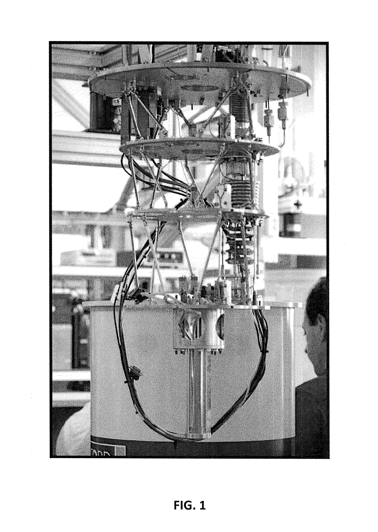
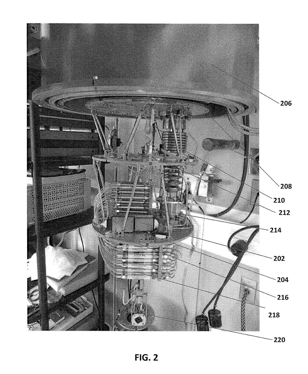
Since approximately 2005, the majority of cryostats sold by Oxford Instruments are so-called cryogenfree dilution refrigerators that employ a pulse tube cooler and cryostat-mounted turbomolecular pump, wherein such a setup allows continuous operation without expensive cryogens (such as liquid helium), but adds electrical noise induced by mechanical vibrations and magnetic induction.
Further, although a huge variety of commercial filters for electrical signal condition near room temperature (−55° C. . . . 100° C. Celsius), none of these are specified to work at cryogenic temperatures.

Method used


Image

  • Reducing noise and temperature during measurements in cryostats
  • Reducing noise and temperature during measurements in cryostats
  • Reducing noise and temperature during measurements in cryostats

Examples


Embodiment Construction

[0029]While this invention is illustrated and described in a preferred embodiment, the invention may be produced in many different configurations. There is depicted in the drawings, and will herein be described in detail, a preferred embodiment of the invention, with the understanding that the present disclosure is to be considered as an exemplification of the principles of the invention and the associated functional specifications for its construction and is not intended to limit the invention to the embodiment illustrated. Those skilled in the art will envision many other possible variations within the scope of the present invention.

[0030]Note that in this description, references to “one embodiment” or “an embodiment” mean that the feature being referred to is included in at least one embodiment of the invention. Further, separate references to “one embodiment” in this description do not necessarily refer to the same embodiment; however, neither are such embodiments mutually exclu...


PUM

PropertyMeasurementUnit
cut-off frequenciesaaaaaaaaaa

Abstract

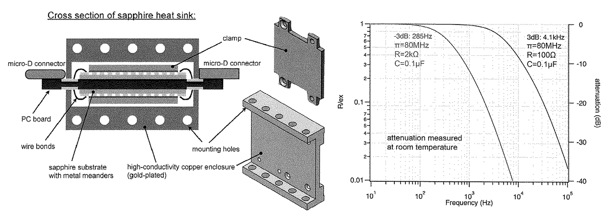
A device is disclosed to reduce noise and temperature during measurements in cryostats comprising, the device comprising any of, or a combination of, the following PC boards, each conditioning a different frequency range: a RC-PC board having a two-stage RC filter in series with a surface-mounted pi-filter; a RF-PC board having a plurality of surface-mounted pi-filters in series, each configured with different low-frequency cutoff frequencies; and a Sapphire-PC board having a sapphire substrate having high heat conductivity at low temperature with thin metal films routed in a meandering fashion.

Description

SPONSORSHIP INFORMATION[0001]This invention was made with government support under Grant No. DMR-0908070 from the National Science Foundation, Grant No. W911NF-10-1-0330 from the U.S. Army / ARO, and Grant No. HR0011-09-1-0007 from the U.S. Department of Defense / DARPA. The government has certain rights in this invention.BACKGROUND OF THE INVENTION[0002]Field of Invention[0003]The present invention relates generally to the field of cryostats. More specifically, the present invention is related to reducing noise and temperature during measurements in cryostats.[0004]Discussion of Related Art[0005]Since the 1960s, the most widely used type of cryostat for low-temperature measurements (i.e. below 1° Kelvin) is the dilution refrigerator. Presently, cryostats are commercially available from a variety of manufacturers (e.g., Oxford Instruments, Leiden Cryogenics, Janis Cryogenics, BlueFors, ICEoxford, and Cryoconcept) and they are used in most low-temperature laboratories world-wide. Typical...

Claims


Application Information

Patent Timeline
Patent Type & Authority Patents(United States)
IPC IPC(8): G01N25/00G10K11/162H05K1/02H05K1/03
CPCH05K1/0204G10K11/162H05K1/0306
Inventor KUEMMETH, FERDINANDMARCUS, CHARLES M.
Owner PRESIDENT & FELLOWS OF HARVARD COLLEGE
Learn More